Knowledge of the Arduino power supply schematic is very important. It can help you choose the right power supply for your Arduino board. Besides, you should give enough attention to the Arduino power supply. Simply because it affects the entire Arduino board operation. More so, it affects the accuracy of the analog to digital converter (ADC).
Main Parts of Arduino Uno Power Supply
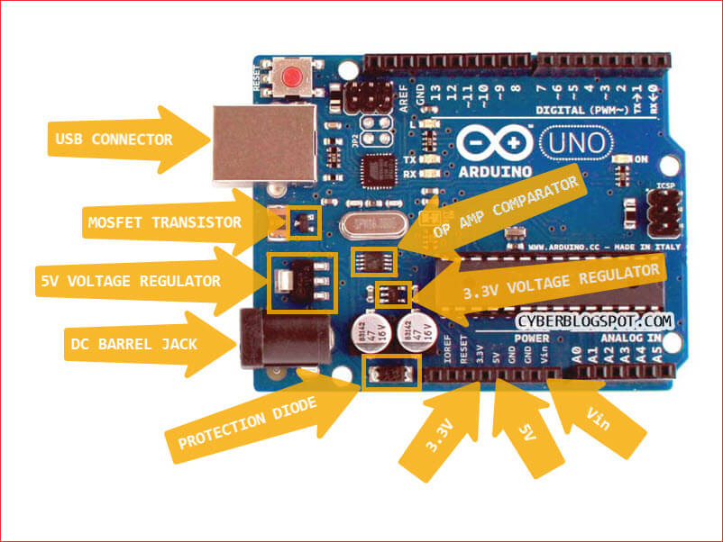
In the picture above, the important parts of the Arduino power supply are all annotated. The main parts of the power supply are the two (2) voltage regulators, the op amp comparator, the MOSFET transistor, and the protection diode.
5V Voltage Regulator
In the original Arduino Uno R3e, this is a NCP1117ST50T3G chip. It is a three-terminal voltage regulator. According to the datasheet, it can output a current in excess of one (1) ampere. Also, it has a maximum dropout voltage of 1.2 volts. In addition to that, it boasts of input operation up to 20 volts.
In the Chinese Arduino clone that I have, the 5V voltage regulator is an AMS1117. A quick check on the datasheet indicates that it is also a 1 ampere voltage regulator. It has a similar dropout voltage of 1.2 volts. However, the maximum input voltage is 18 volts, a two (2) volts difference from the NCP1117. Anyway, both AMS1117 and NCP1117 are the same 1117 device from two different manufacturers.
3.3V Voltage Regulator
Again, on the original Arduino board, the chip used for the regulator is LP2985-33DBVR. It is a Low Dropout device (LDO). That is, the difference between the input and output voltages is very small. The maximum dropout voltage of the device is 280mV. Also, the device has a maximum current of 150mA and a maximum input voltage of 16 volts.
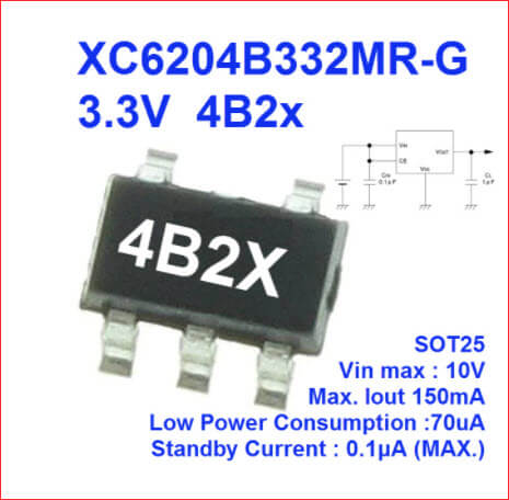
On the Chinese clone, the 3.3V voltage regulator is also different. As a matter of fact, the chip is only marked as “4B2X”. If you try to google the part number to look for the datasheet, you will end up empty handed. However, a website selling the chip claims that the part number is XC6204B332MR-G (see screenshot below). If it is true, then the chip has similar output current and dropout voltage as the original. The output current is 150mA and the dropout voltage is 200mV. However, the input voltage is only up to 10 volts, a far 6 volts lower than the original.
OP AMP Comparator
Let’s take a look at the operational amplifier (Op Amp) that is used as a comparator. The Arduino Uno from Italy uses the LMV358IDGKR chip. There seems nothing special here, because LMV358 is just a low voltage version of the ever popular LM358 op amp chip. Suffice to say that the chip is a general purpose operational amplifier with two op amps in a single package.
Unfortunately, I cannot identify the op amp chip on my Arduino clone. It is only marked as “88 TI”.
MOSFET Transistor
The MOSFET transistor used on the Arduino board is the FDN340P transistor. It is a P-channel MOSFET transistor with a rating of 2A drain current. It’s maximum drain to source voltage is 20V.
The Arduino clone uses the transistor A1SHB. According to datasheetspdf.com, this transistor is a generic Si2301 transistor. Also, their datasheet shows that it is a P-channel MOSFET transistor with 2.5A drain current rating. It’s maximum drain to source voltage is also 20 volts, like the FDN340P.
Protection Diode
The protection diode (polarity reversal protection) installed is M7. This is a surface mount (SMD) version of the general purpose 1N4007 diode. Therefore, as in the regular through-hole diode, it has a 1 ampere maximum forward current rating. Its maximum RMS voltage is 700 volts.
At last, I found a matching part on the Chinese clone. The clone uses the same M7 diode that is on the original Arduino Uno board.
Now that we are familiar with the parts of the power supply, let’s take a look at the schematic diagram.
Arduino Uno Power Supply Schematic Diagram
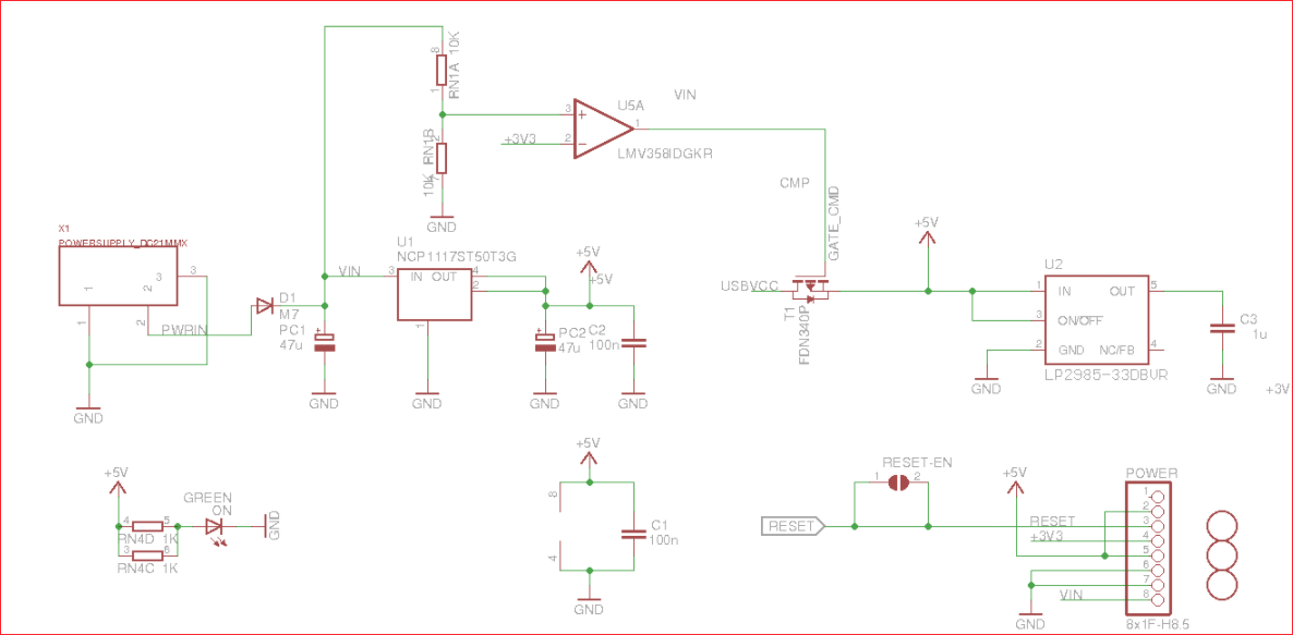
Shown above is the power supply schematic diagram of an Arduino Uno R3 board. It shows that the DC jack connects to the 5.5V voltage regulator. It also shows how the USBVCC from the USB connector supplies power to the board. To understand the circuit better, I made a simplified schematic diagram based on the circuit above.
The Simplified Arduino Uno Power Supply Schematic
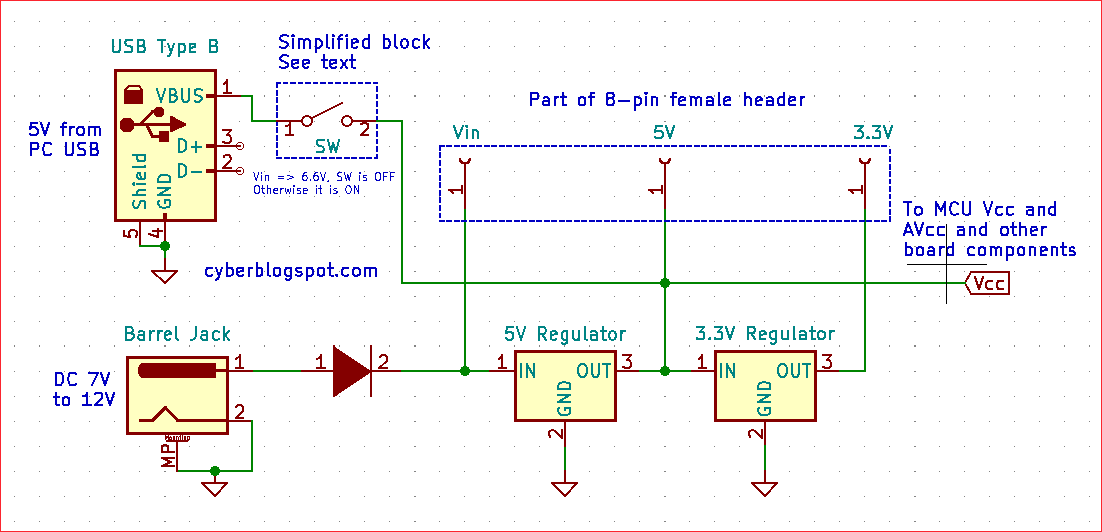
Shown above is a simplified schematic diagram of an Arduino Uno power supply. It is based on the Arduino Uno schematic diagram from the official site.
Let us start from the DC Barrel Jack. If we connect a DC power source on the DC jack, the supplied voltage will first pass thru a protection diode. Then, it enters the 5-volt voltage regulator and comes out as a regulated 5 volts on the VCC terminal. As noted on the diagram, the VCC provides all the power requirements of the whole Arduino board. Take note that the VCC also connects to the 8-pin female header and labelled as 5V.
The 5-volt output of the regulator is also fed to the input of the 3.3V voltage regulator. It comes out as a 3.3 volts that also terminates on the female header with a 3.3V label. Observe that this 3.3V does not supply anything on the Arduino board. Its main purpose is for supplying external circuits with 3.3 volts. Its only use within the Arduino board is serving as a voltage reference for controlling the USB connector voltage.
Finally, the simplified schematic shows that the USB connector connects to the 5V (and hence, VCC) thru a simplified switch. Let’s find out how the switch works.
How the Auto Switching of USB Power Works
Anyway, why, in the first place, is there a need for a switch on the USB connector? The schematics above show that the Arduino board accepts power in many ways. As a matter of fact, in four different (4) ways. As a result, two or more input voltages may compete in supplying power to the board. To prevent this from happening, Arduino monitors the Vin for the presence of any voltage. Hence, the need for a switch. If Arduino finds an external voltage coming from either the Vin or the DC jack, it disconnects the USB connector VBUS (+5V) voltage.
If you look closely at the simplified schematic above, you will see that you should not simultaneously power the DC jack and the Vin pin. Also, you must refrain from powering the 5V pin together with the USB connector.
So basically, the Arduino board only monitors the USB connector and the Vin input voltages. However, since the DC jack is also connected to the Vin line, it is also compared with the USB connector when it is powered up (instead of the Vin input).
The Op Amp Comparator
The op amp (LMV388) samples the Vin line thru a voltage divider (refer to the schematic above). Because the voltage divider uses two resistors of the same value, the voltage sampled is one half (1/2) of the Vin voltage. This sampled Vin voltage is then compared to the output of the 3.3 volts regulator. When the sampled Vin voltage is greater than or equal to 3.3 volts (>=3.3V), the op amp output goes up. As a result the MOSFET transistor turns off. Subsequently, the USB connector voltage is disconnected from the 5V (or VCC) line.
On the other hand, when the voltage from Vin disappears or goes down below 6.6 volts, the comparator turns on the MOSFET transistor. As a result, it will allow the input voltage from the USB to connect to the 5V supply line.
Four Ways of Powering Up The Arduino Power Supply
Based on the schematics above, we can see that there are four (4) different ways of powering up an Arduino board. These are:
- USB Connector
- DC Barrel Jack
- Vin on the 8-pin female header
- 5V on the 8-pin female header
USB Connector
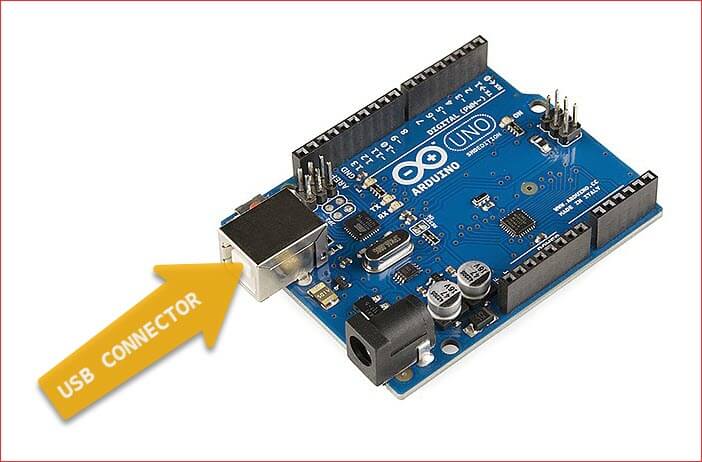
First, you can power the Arduino board using the USB connector. This is one of the standard ways of supplying power to the Arduino Uno board. When you buy an Arduino Uno board, it usually comes with a USB data cable. This cable, when plugged into a PC, carries a 5V DC voltage on one of its terminals.
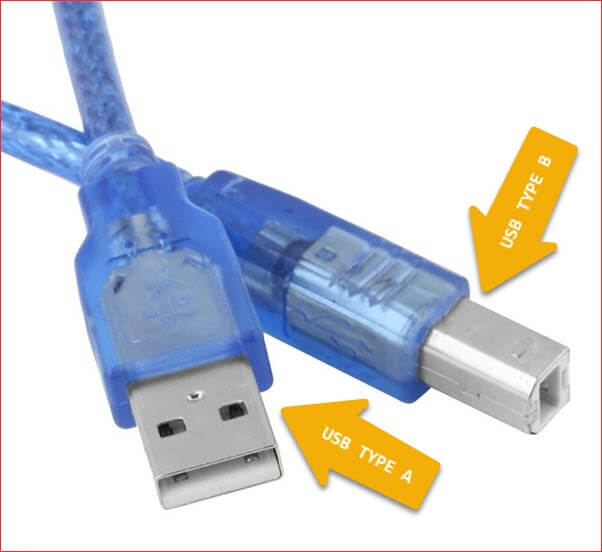
The cable uses a Type A male USB connector on one end that connects to a PC. The other end that connects to the Arduino board itself is a Type B male USB connector. A picture of the cable connectors is shown above.
DC Barrel Jack
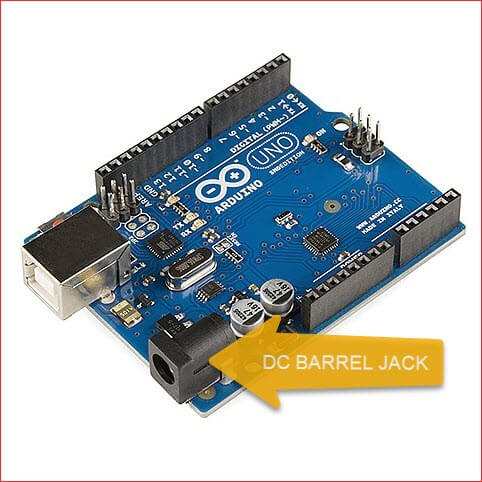
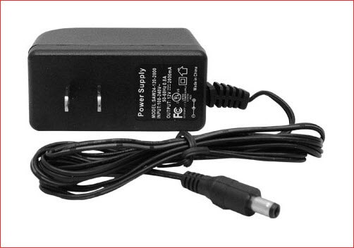
The second way of powering Arduino is thru the DC Barrel Jack. Typically, the DC jack is connected to a 9V or 12V AC-DC adapter. There are several requirements here for using the DC barrel jack. First of all, make sure that the output of the adapter is a direct current (DC). Second, check the voltage polarity. The inside terminal of the plug must be positive while the outside terminal must be negative. Third, the output voltage of the DC adapter must be at least 7 volts. And finally, the output voltage of the adaptor may not exceed 12 volts. Also, the recommended input voltage to the board is 9 volts.
Why is there a 7 volts minimum and a 12 volts maximum requirements on the DC barrel jack?
The Minimum Requirement
The schematics above show that the input voltage from the DC barrel jack passes thru a diode. The diode serves as a protection for polarity reversal. That is, if you plugged a DC power adapter that is wired differently (outside terminal positive, instead of negative), you will not damage your Arduino. However, the diode has a voltage drop of around 0.7 volts (can be as high as 1.1V). This reduces the input voltage being fed to the board. Also, the input voltage will pass thru a 5V voltage regulator. The regulator requires a voltage input of at least 1.2 volts higher than its output. That is, it needs at least 6.2 volts to operate properly. Adding the 0.7 volts diode drop to the 6.2 volts input requirement, the total is 6.9 volts. Hence, the required 7 volts minimum input voltage for the DC barrel jack.
The Maximum Requirement
With regards to the 12V maximum requirement, it has something to do with the power dissipation on the voltage regulator. For proper operation, voltage regulators require a higher voltage on its input than the required output. But raising the input voltage more than necessary has a negative effect on the voltage regulator. The excess input voltage produces excess power that has to be dissipated by the regulator. Therefore, using an input voltage greater than 12 volts could exceed the dissipation rating of the regulator. In other words, with too much input voltage, the regulator overheats and eventually gets fried.
The Recommended Input Voltage
As previously stated, the recommended input voltage for the DC barrel jack is 9V. It is in between the minimum and the maximum input voltages.
Power Thru Vin Pin Terminal
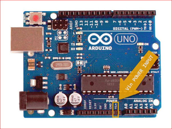
Powering the Arduino board thru the Vin terminal is basically the same as using the DC barrel jack. It is clear from the schematics above that the only difference is the polarity protection diode. Therefore, the requirements should be similar with the DC barrel jack.
Power Via 5V Pin Terminal
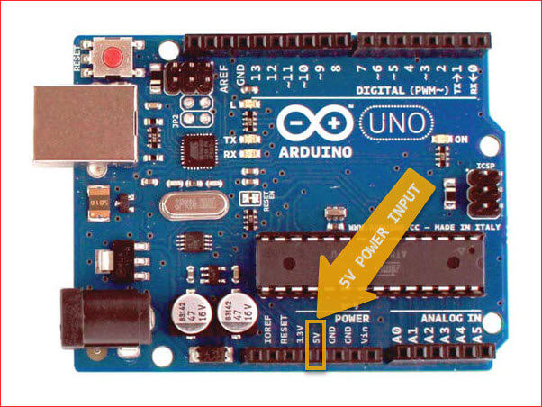
Finally, you may power the Arduino Uno board directly thru the 5V pin terminal. Based on the schematics, the 5V pin terminal connects directly to the VCC. This means it bypasses the diode polarity protection and the 5V voltage regulator. As a result, it loses the protections afforded by these circuits. That is, it loses the polarity reversal protection by the series diode and the built-in current limiting protection of the 5V voltage regulator.
Also, besides losing some protections, be aware that the input voltage to the 5V terminal must be clean and well regulated. Furthermore, powering this terminal with a voltage greater than 6V may possibly break your Arduino board. The reason is that the ATMEGA328 chip has an absolute maximum rating of 6 volts.
Related Articles on Arduino Power Supply Schematic
1 – How to Use MCP4921 DAC with Arduino
2 – How to Use MCP4725 Module with Arduino
3 – How to Use ADS1220 ADC Module with Arduino
4 – How to Set up Arduino IDE for ESP8266 Programming
5 – How to Install Esptool on Windows 10
6 – NodeMCU ESP-32S Pin Configuration
7 – NodeMCU V3 ESP8266 Pinout and Configuration
8 – How to Save and Restore ESP8266 and ESP32 Firmware
9 – How to Control ESP-01 Without a Router
10 – How to Test NodeMCU V3 Using Esptool
References on Arduino Power Supply Schematic
1 – Arduino Uno on Wikipedia – the first thing to read when doing a research
2 – Arduino Uno Schematic Diagram – complete documentation including interactive board viewer
3 – Arduino Pro Mini clones 12V supply and 4B2X regulator – Arduino with 4B2X regulator getting fried
4 – Convert Arduino Uno Power Supply to 3.3 Volts – Adafruit Arduino Tips, Tricks, and Techniques
5 – FDN340P Drawn incorrectly on schematic – Discussion on a possible MOSFET erratum on Arduino Uno
hi there,
Thanks for the detailed explanation.
Understand that there is a P-channel enhancement MOSFET on the arduino power supply circuit.
Is that P-MOSFET conductive when do not have any power sources are connected to the arduino? If it is not conductive, how can the USB get connected to the arduino power supply circuit?
Please advise.
Regards
hi there, is the P-channel MOSFET (labelled as T1) conductive when there is no power source connected to the arduino?