Arduino Reference and Resources is a collection of my personal blogs and other relevant information I find useful. All the Information that I come across and find interesting are bookmarked here.
Software
How to Install Arduino IDE on Windows 10
How to Set up Arduino IDE for ESP8266 Programming
How to Install Esptool on Windows 10
Hardware/Software
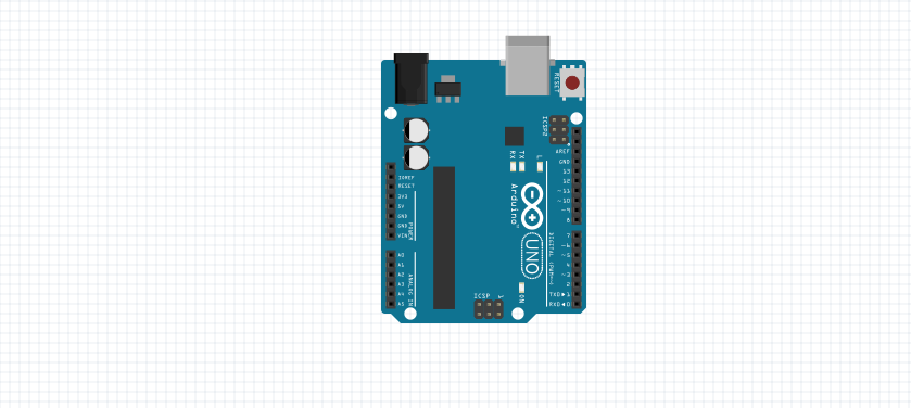
Arduino Uno
ESP8266 and ESP32
How to Save and Restore ESP8266 and ESP32 Firmware
How to Compute Resistor Value for LED
ESP8266 ESP-01
How to Control ESP-01 thru a Router
How to Control ESP-01 Without a Router
ESP-01 with RTC and LCD Display
ESP-01 ESP8266 NTP Clock with LCD Display
How to Program ESP-01 with Arduino IDE
ESP8266 NodeMCU V3
NodeMCU V3 ESP8266 Pinout and Configuration
How to Test NodeMCU V3 Using Esptool
How to Test NodeMCU V3 ESP8266 Development Board
How to Connect a DS3231 to NodeMCU V3
ESP32
NodeMCU ESP32S Pin Configuration
Arduino Uno R3
20×4 LCD with I2C
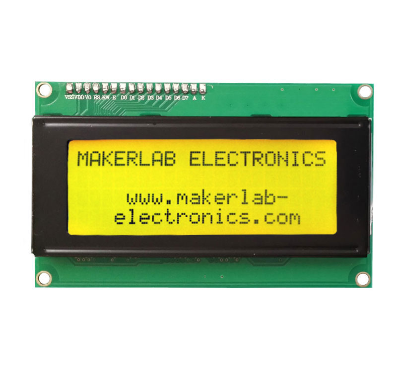
LCD Display Connection
Connect I2C Serial LCD Module to Arduino UNO as following :
- VCC to 5V
- GND to GND
- SDA to A4
- SCL to A5
Arduino Sketch from LiquidCrystal_I2C Library
//YWROBOT
//Compatible with the Arduino IDE 1.0
//Library version:1.1
#include <Wire.h>
#include <LiquidCrystal_I2C.h>
LiquidCrystal_I2C lcd(0x27,20,4); // set the LCD address to 0x27 for a 16 chars and 2 line display
void setup()
{
lcd.init(); // initialize the lcd
lcd.init();
// Print a message to the LCD.
lcd.backlight();
lcd.setCursor(3,0);
lcd.print("Hello, world!");
lcd.setCursor(2,1);
lcd.print("Ywrobot Arduino!");
lcd.setCursor(0,2);
lcd.print("Arduino LCM IIC 2004");
lcd.setCursor(2,3);
lcd.print("Power By Ec-yuan!");
}
void loop()
{
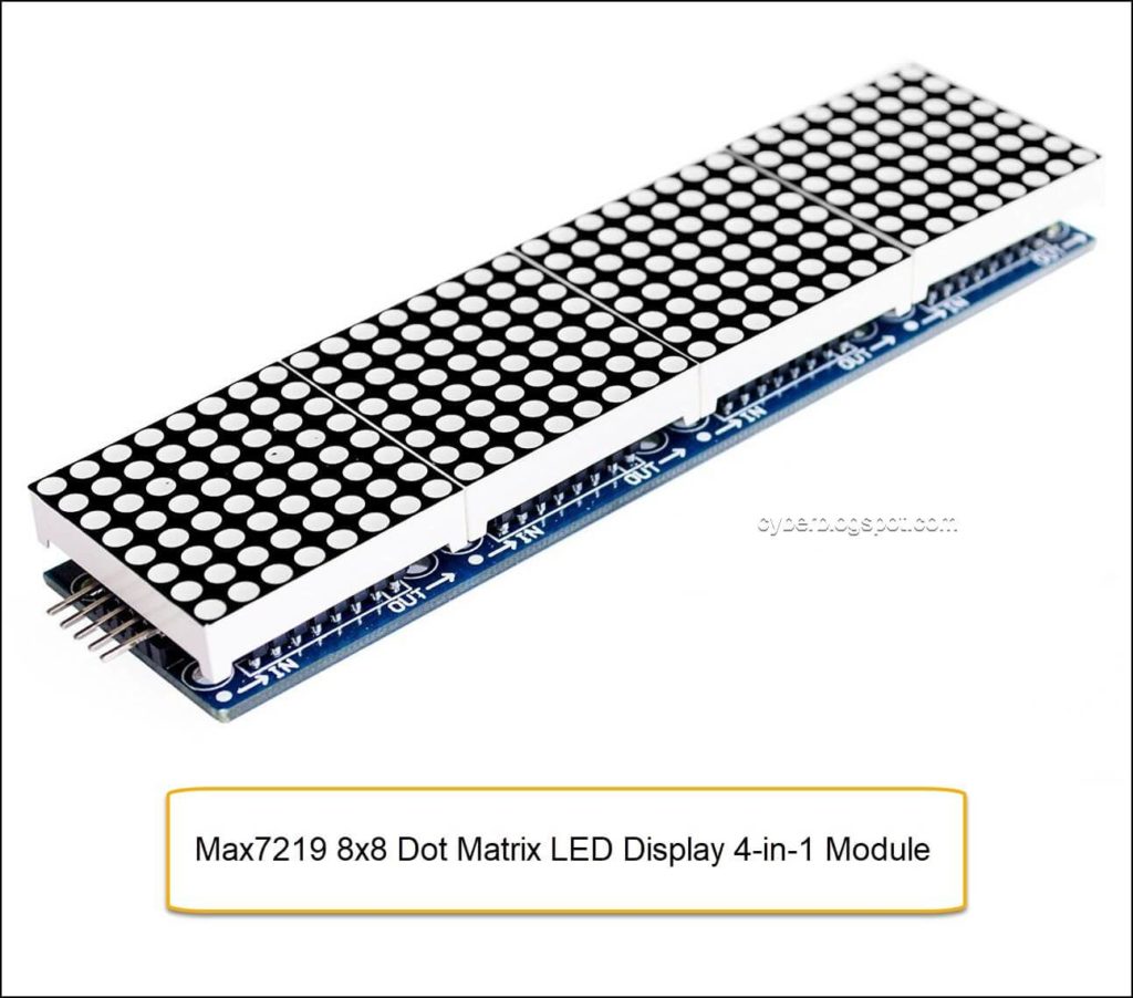
}Max7219 8×8 Dot Matrix LED 4-in-1 Display Module
This display module consists of four (4) 8×8 LED Dot Matrix Display, each driven by a Max7219 chip. The four Dot Matrix Display are daisy chained together to form the 4-in-1 display module.
The Max7219 display driver chip reduces the GPIO pins needed to control the whole display module. A microcontroller, such as Arduino Uno, interfaces with it using only three (3) GPIO pins.
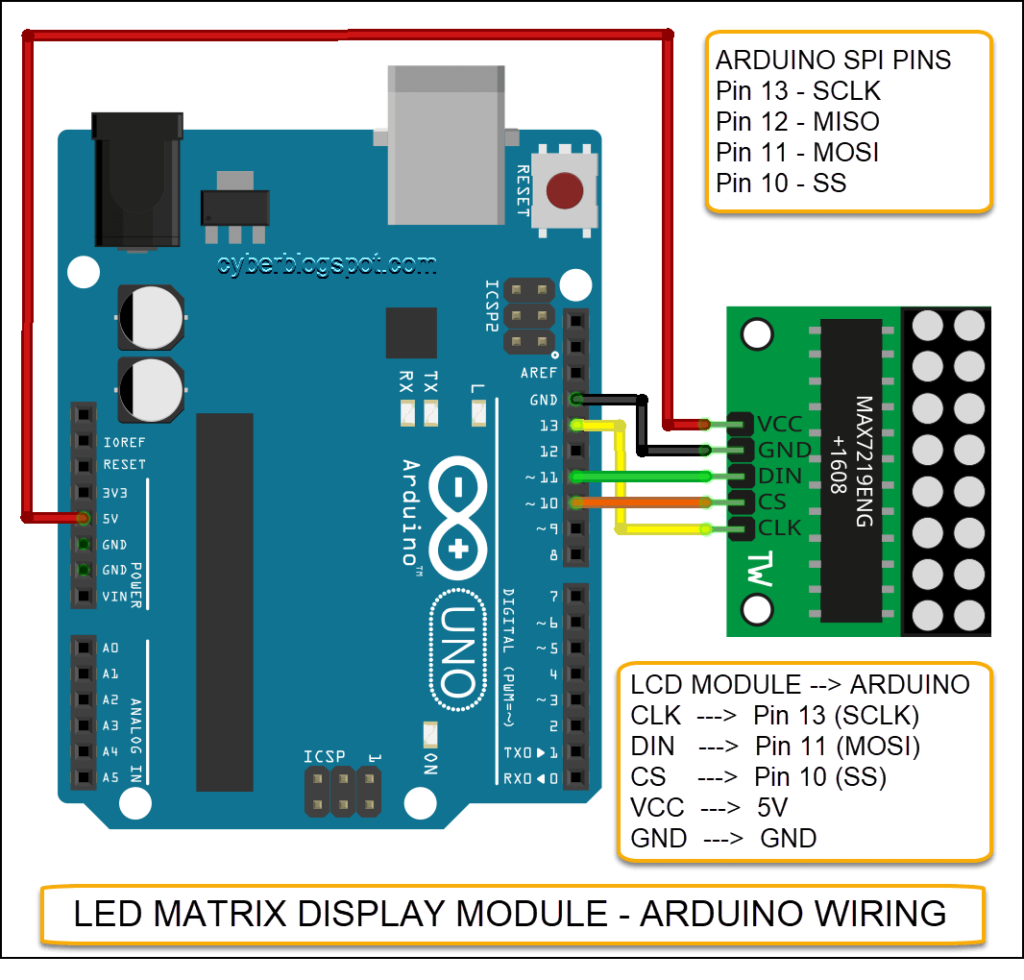
Microcontroller Wiring
The Max7219 LED Dot Matrix Display Module may be connected to Arduino Uno using the SPI pins.
| ARDUINO SPI PINS | MAX7219 Display Module |
| 13 (CLK) | CLK |
| 11 (MOSI) | DIN |
| 10 (SS) | CS |
| VCC | VCC |
| GND | GND |
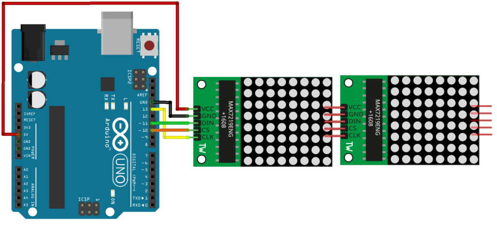
Connection to non-SPI Arduino Pins
If you look at some Arduino projects on the net, they are wired like this:
| ARDUINO PINS | MAX7219 Display Module |
| 12 | DIN |
| 11 | CLK |
| 10 | CS |
| VCC | VCC |
| GND | GND |
Do they work? Can the Max7219 display module actually be connected to any three (3) available digital I/O pins on Arduino?
The answer is yes and no. It depends on the library files that you use to program the display module.
Actually, the wiring above is used by a popular Max7219 display library, the LedControl library available in https://github.com/wayoda/LedControl. It does not use Arduino’s hardware SPI (it means it does not reference or make any call to Arduino’s SPI library, SPI.h). Hence, the display module may be connected to any three available IO pins on Arduino.
I never changed the LedControl implementation because (for me) one of the main features is that you can use any 3 IO-Pins to connect your device. You are not tied to the Hardware-SPI pins.
wayoda, https://github.com/wayoda/LedControl/issues/8
In an application where high speed is a requirement, a library that uses Arduino’s built-in SPI hardware may have to be used. In such a case, you must connect your Max7219 display module to Arduino’s SPI I/0 pins ( pins 10 to 13).
Wayoda’s LedControl library is also available on Arduino IDE’s Library Manager.

Sample Clock Project Using LedControl Library
Sample Clock Project Using MD-MAX72xx and MD_Parola Library
https://github.com/AnthoTronics/Ardunio-Clock-Project
Why is my Max7219 display module displaying texts in reversed order or upside down? It’s because your module is wired differently. There are four ways to wire a Max7219 display module.
Parola A to Z – Adapting for Different Hardware, https://arduinoplusplus.wordpress.com/2017/04/14/parola-a-to-z-adapting-for-different-hardware/
1024 LED Matrix WiFi Message Board with Menu + Web Interface
https://www.hackster.io/ericBcreator/1024-led-matrix-wifi-message-board-with-menu-web-interface-1b2666#team
Arduino Parola Zone Time Msg Display – Multi-colored LED’s
https://www.instructables.com/id/Arduino-Parola-Zone-Time-Msg-Display/
Description
This module is actually 4 pcs of 8×8 LED Matrix.
https://www.makerlab-electronics.com/product/8×8-dot-matrix-led-display-module-max7219/
https://www.instructables.com/id/User-Manual-MAX7219-Dot-Matrix-4-in-1/
Library
https://playground.arduino.cc/Main/LEDMatrix/
Controlling a Led matrix or 7-segment displays with the MAX7219 or the MAX7221
https://playground.arduino.cc/Main/LedControl/
LedControl – Arduino Library for Max7219 and 7221 – Tutorial
Library on Github – https://github.com/wayoda/LedControl/blob/master/src/LedControl.cpp
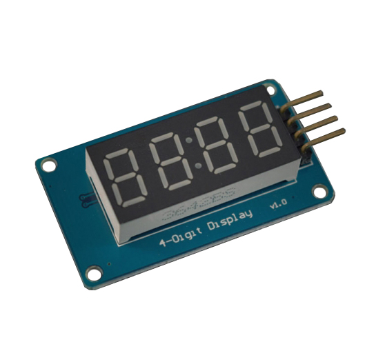
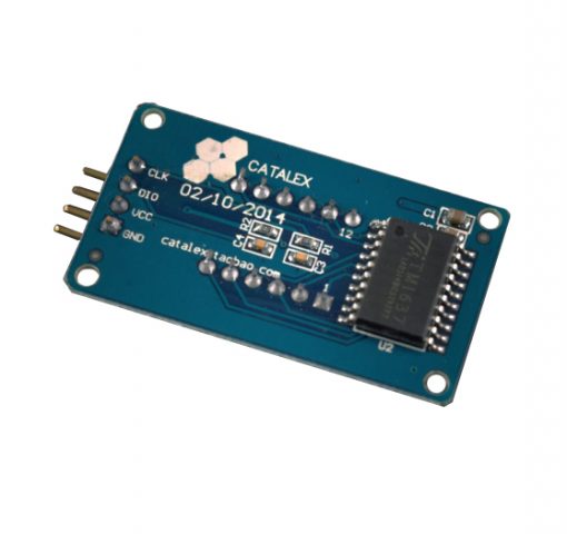
4 digit LED module TM1637 7 segment display
TM1637 is a chip for driving 7-segment displays. There are several modules using this chip to form a 4 digit numerical display module (sometimes called “Digital Tube”).


Fritzing
Fritzing is an open-source program for designing electronic circuits.
sudo apt-get install friitzing
sudo apt-get install fritzing-parts
Open fritzing on the launcher and not on the terminal.
ESP8266 ESP-01 Wi-fi Module
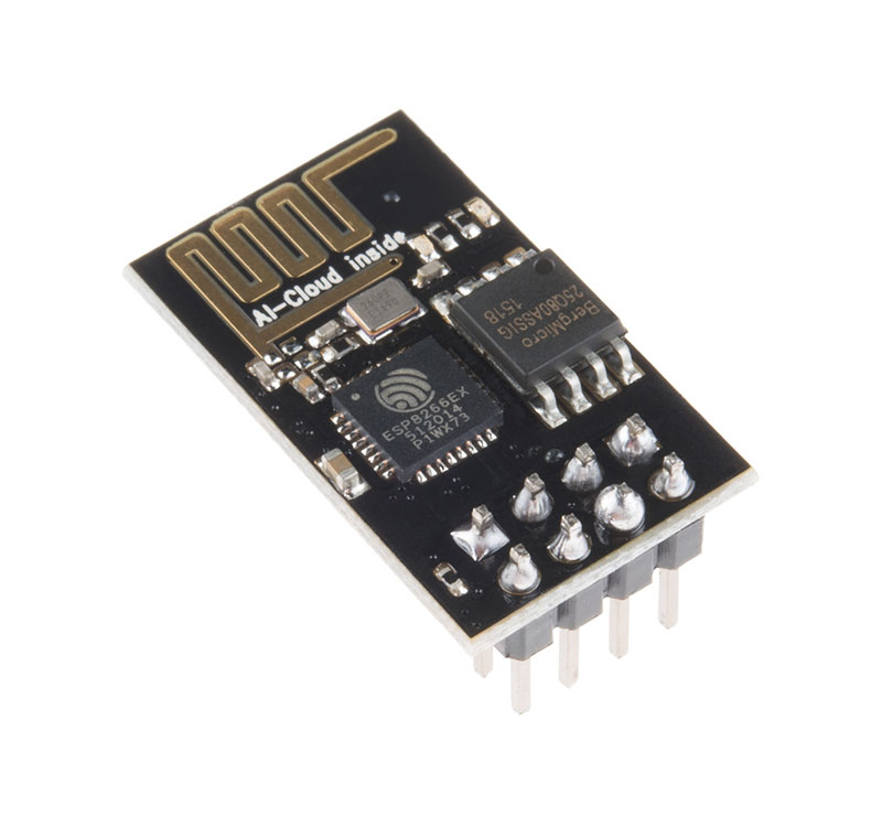
ESP8266 is a microcontroller chip integrated with Wi-fi capability. The chip does not have flash memory, so Wi-fi modules incorporate an external flash memory.
The ESP8266 ESP-01 Wi-fi Module shown above uses 1MB flash memory chip.
Take a look at ESP-12 and ESP-32
AT Commands
AT
AT+CWMODE?
AT+CWMODE=n, sta=1, ap=2, both=3
AT+CIFSR - get local ip address
AT+CWJAP= “Wi-FiNetwork”,“Password”
AT+CIPMUX=n - multiplex mode, 0-single, max 4
AT+CIPSERVER=1,80 - create server
AT+CIPSEND=0,5
AT+CIPCLOSE=0
https://www.instructables.com/id/Using-ESP-01-and-Arduino-UNO/
https://jayconsystems.com/
https://jayconsystems.com/blog/getting-started-with-the-esp8266-esp-01
https://jayconsystems.com/blog/using-esp-01-and-arduino-uno
https://jayconsystems.com/blog/esp8266-as-a-microcontroller
Wiring diagram for level conversion https://www.quora.com/Why-does-ESP8266-give-error-message-on-AT-command
ARDUINO TIME SYNC FROM NTP SERVER USING ESP8266 WIFI MODULE
http://www.geekstips.com/arduino-time-sync-ntp-server-esp8266-udp/
Confusion on ESP8266 Library – https://forum.arduino.cc/index.php?topic=508665.0
How to Flash ESP-01 Firmware to the Improved SDK v2.0.0
https://www.allaboutcircuits.com/projects/flashing-the-ESP-01-firmware-to-SDK-v2.0.0-is-easier-now/
How to Flash ESP-01 Firmware to the Improved SDK v2.0.0 – https://www.allaboutcircuits.com/projects/flashing-the-ESP-01-firmware-to-SDK-v2.0.0-is-easier-now/
Restoring the AT firmware on the ESP8266 – https://robertoostenveld.nl/esp8266-at-firmware/
reset causes:
    0:
    1: normal boot
    2: reset pin
    3: software reset
    4: watchdog reset

boot device:
    0:
    1: ram
    3: flash
Reference on ESP8266
AT Commands – https://room-15.github.io/blog/2015/03/26/esp8266-at-command-reference/
AT Commands: – http://www.pridopia.co.uk/pi-doc/ESP8266ATCommandsSet.pdf
ESP8266 module comparison: ESP-01, ESP-05, ESP-12, ESP-201, Test Board and NodeMCU
https://blog.squix.org/2015/03/esp8266-module-comparison-esp-01-esp-05.html
ESP8266EX Datasheet – https://www.espressif.com/sites/default/files/documentation/0a-esp8266ex_datasheet_en.pdf
ESP8266 Wikipedia – https://en.wikipedia.org/wiki/ESP8266
NodeMCU Variant – https://medium.com/wemaker/nodemcu-variant-62117b608eef
Using ESP8266 GPIO0/GPIO2/GPIO15 pins – http://www.forward.com.au/pfod/ESP8266/GPIOpins/index.html
How to Use the ESP8266-01 Pins and Leds – https://www.instructables.com/id/How-to-use-the-ESP8266-01-pins/
1024 LED Matrix WiFi Message Board with Menu + Web Interface
1024 LED Matrix WiFi Message Board with Menu + Web Interface
The Mighty ESP-01 Adapter – https://www.electroschematics.com/the-mighty-esp-01-adapter/
A Beginner’s Guide to the ESP8266 – Pieter P, 08-03-2017
https://tttapa.github.io/ESP8266/Chap01%20-%20ESP8266.html
Different Programming “Runtimes” https://electronics.stackexchange.com/questions/286328/esp8266-elua-nodemcu-vs-micropython –
Six of the most popular ESP8266 “runtimes”:
- AT Command SET. Popular when the 8266 is paired with another MCU. Communicates via the serial port. ~64k of 128k RAM available.
- MicroPython. A MicroPython script interpreter with user friendly GUI that can be accessed via the serial port or WIFI/IP. ~30k of 128k RAM available.
- Lua/NodeMCU. A LUA script interpreter with user friendly GUI that can be accessed via the serial port. ~40k of 128k RAM available.
- JavaScript/Espruino. A JavaScript interpreter with user friendly GUI that can be acess via the serial port or WiFi/IP. ~20k of 128k RAM available.
- C/IDE-12E. ESP8266 flashing tool & C libraries/tools using the standard Arduino IDE. ~80k of 128k RAM available.
- C/ESP8266_SDK. C libraries/tools from the manufacturer. Also a collection of example applications. ~512k Flash. Guesstimate 80k of 128k RAM available.
The key insight is that the bulk of the code is common. The primary libraries in 1-5 all originate from 6. Beneath a thin layer of AT/Python/LUA/JavaScript/C the primary code is practically identical. That means performance (RAM, FLASH, execution) is similar too.
Since you seem concerned about speed and RAM (flash is generally OK) how about option #5? Arduino is a usable IDE with a large collection of examples. You could have your first code running in less than an hour and would likely outperform any of the scripting engines.
In the absence of significant memory usage differences I would choose MicroPython due to the greater number of libraries and an active online community with IRC webchat. Documentation for adding C modules has improved.
Option #6 provides you with the highest potential for optimization but at higher complexity and steeper learning curve.
Lastly a good ESP8266 rule-of-thumb: Each TCP/IP connection can consume up to ~3k of memory. Always expect less than 5 simultaneous connections!
TL;DR: ESP8266 applications have most of their code in common and perform similarly. So choose the script engine you like or step up to C/IDE-12E. Don’t expect more than 5 simultaneous IP connections.
Arduino Software
https://www.arduino.cc/en/Main/Software
How to Use Arduino Web Editor
When building your sketch, we will always look at your custom libraries first, your favorites next, and then Arduino built-in libraries.
https://blog.arduino.cc/2016/11/22/the-library-manager-is-now-available-on-the-web-editor/
Fritzing
Search icon missing – delete or remove the parts and bin folders