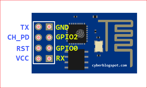
The ESP-01 Wi-Fi module is one of the most popular ESP8266-based microcontroller board. It is very inexpensive and widely available. If you are new with ESP-01 modules, or are contemplating on buying one, you are lucky for visiting this page. We have here all the necessary information on the difference between ESP-01 and ESP-01S Wi-Fi modules.
The ESP-01 module and the ESP-01S module are functionally the same. However, knowing the difference between the two is very important because it can affect how you wire them to external circuits. Also, the boards have different current consumption owing to their difference in the number of onboard LEDs.
ESP-01S is a Newer Version
First off, the ESP-01 module was the original version that was popularized almost a decade ago. The ESP-01S is the newer version. At the time of this writing, circa 2023, the original ESP-01 module is still widely available. Most online stores would allow you to choose between an ESP-01 or an ESP-01S. But some stores may sell you an ESP-01 for an ESP-01S, or vice versa.
Difference in Physical Appearance
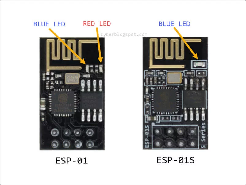
At first glance, the two modules look the same. However, a close examination of the boards will show the difference in the number of LEDs (Light Emitting Diodes). Please see Figure 2 below. In the original ESP-01, there are two (2) small LEDs. On the other hand, the ESP-01S has a single, bigger LED.
The difference becomes more apparent when you supply power to the boards. The ESP-01 board will have a red LED light turned on indicating the presence of power. On the ESP-01S board, you will only see a blue LED flash for a while when the power is applied.
The Blue LED Wiring Difference Between ESP-01 and ESP-01S
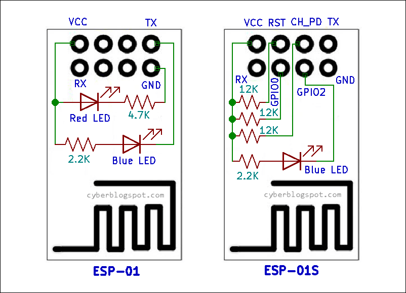
Although both boards have a blue serial-activity LED, the blue LEDs are wired differently. See Figure 3. In the ESP-01 board, the blue LED is connected on the VCC and the TX pins, while on the ESP-01S, it is connected on the VCC and the GPIO2 pins. On both boards, a 2.2K ohms resistor is used in series with the blue LED as a current limiter.
Pull-up Resistors on ESP-01S
Another difference between ESP-01 and ESP-01S is the presence of three (3) pull-up resistors on the ESP-01S module. Pull-up resistors are used to provide a logic HIGH signal to a circuit. As shown on the right side of Figure 3 above, three (3) 12K-ohm resistors are connected from the VCC to the RESET, GPIO0, and CH_PD pins on the ESP-01S board.
Prior to the availability of the ESP-01S module, a popular ESP-01 wiring scheme for adding a reset switch and a programming switch is shown below in Figure 4. First of all, in order to power up the ESP-01 board, you need to pull up the CH_PD (Chip Enable/Power Down) pin. Next, you connect the RESET pin to the VCC because you do not want the RESET pin hanging and be vulnerable to noise causing unexpected resets. And third, pulling up the GPIO0 pin to VCC will automatically run the program or sketch loaded on the ESP-01 module after a power up or a reset.
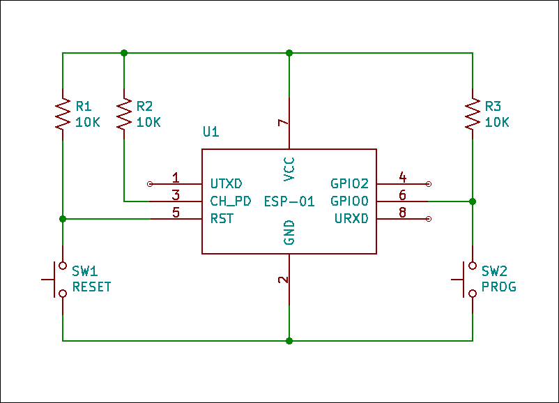
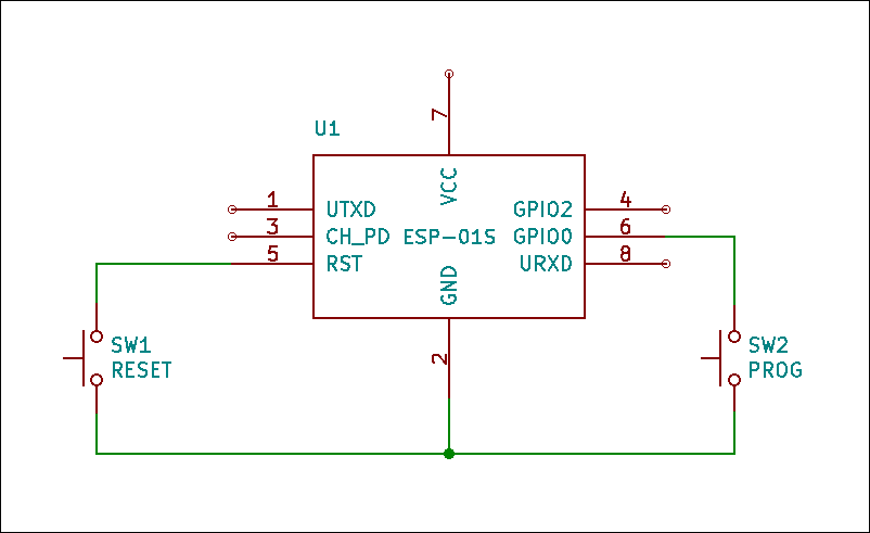
On the newer ESP-01S module, the circuit shown above will be a lot more simple. There is no need to externally supply the three (3) pull-up resistors. See Figure 5.
Summary on Difference Between ESP-01 and ESP-01S
The ESP-01 and the ESP-01S Wi-Fi modules are functionally the same. The ESP-01S module is a newer version of the original ESP-01 module. The ESP-01 module has a red power indicator LED that is absent on the ESP-01S. Both modules have a blue LED that indicates serial activity. However, the blue LED is wired differently on each module’s version. And finally, the ESP-01S module has three (3) on board pull-up resistors that are missing on an ESP-01 module.
Related Articles
How to Program ESP-01 with Arduino IDE
How to Set up Arduino IDE for ESP8266 Programming
How to Test an ESP-01 ESP8266 Module
How to Control ESP-01 thru a Router
How to Control ESP-01 Without a Router
ESP-01 with RTC and LCD Display
How to Save and Restore ESP8266 and ESP32 Firmware
NodeMCU V3 ESP8266 Pinout and Configuration
How to Test a NodeMCU V3 ESP8266 Dev Board
How to Use AT-09 BLE with Arduino and Smartphone
References on Difference Between ESP-01 and ESP-01S
ESP8266 on Wikipedia
ESP8266 Boot Process
Hello, thank you for this very explicit and well-documented tutorial. there is no difference in the amount of flash memory between the two models?