ESP-01 and its latest version ESP-01S are popular microcontrollers with Wi-Fi networking capabilities. They are part of the ESP8266 family of microcontrollers manufactured by Espressif Systems. In this article, we will learn the ESP-01 and ESP-01S pinout and configuration in actual applications.
ESP-01 Wi-Fi Module Specifications
Power Supply:
Voltage 3.0V ~ 3.6V
Current >300mA
Current Consumption:
Continuous Transmission: Average: ~ 71mA, Peak: 300mA
Modem Sleep: ~20mA
Light Sleep: ~2mA
Deep Sleep: ~0.02mA
SPI Flash Memory:
Default 8Mbit (1MB)
Interface:
UART/GPIO
IO Port:
2
UART Baud Rate:
Support 300 ~ 4608000 bps
Default 115200 bps
Frequency Range:
2412 ~ 2484MHz
Transmit Power:
802.11b: 16±2 dBm (@11Mbps)
802.11g: 14±2 dBm (@54Mbps)
802.11n: 13±2 dBm (@HT20, MCS7)
Receiving Sensitivity:
CCK, 1 Mbps : -90dBm
CCK, 11 Mbps: -85dBm
6 Mbps (1/2 BPSK): -88dBm
54 Mbps (3/4 64-QAM): -70dBm
HT20, MCS7 (65 Mbps, 72.2 Mbps): -67dBm
For a complete specifications, you may refer to the ESP-01 Product Specification PDF.
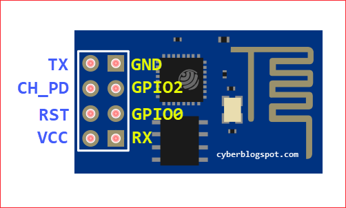
ESP-01 and ESP-01S Pinout
Have you just bought a new ESP-01 Wi-Fi module? Take a look at
How to Test an ESP-01 ESP8266 Module
Learn how to differentiate between ESP-01 and ESP-01S Wi-Fi modules, see:
Difference Between ESP-01 and ESP-01S
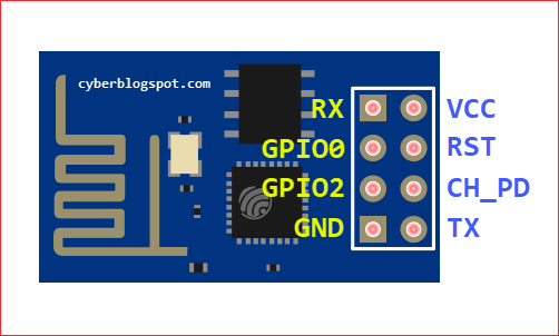
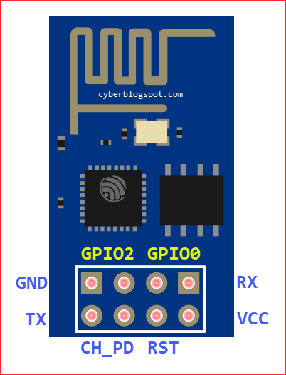
ESP-01 Pin Descriptions
TX – UART0 data send (transmit) pin, also known as GPIO1.
RX – UART0 data receive pin, also known as GPIO3.
CH_PD – Chip Power Down (also known as CH_EN or Chip Enable) – Chip enable pin, active high
RST – External reset pin, active low
GPIO2 – General Purpose Input / Output
GPIO0 – General Purpose Input / Output
VCC – +3.3 Volts Supply Positive
GND – Ground – Supply negative
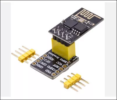
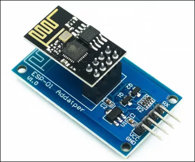
ESP-01 Module Breadboarding and Adapters
When breadboarding, you can not insert the ESP-01 module as it is. A few years ago, you do all sort of tricks to breadboard an ESP-01 module, from bending the header pins to making your own DIY adapter. Luckily, now you can buy a cheap breadboard adapter for the ESP-01 module. See Figure 5.
If you will be connecting the ESP-01 board to an Arduino board, you must remember two (2) things:
- Do not supply the ESP-01 module with the 3.3V output from the Arduino board – the ESP-01 module, as per specification above, may require up to 300mA of current. The 3.3V regulator on the Arduino board may overheat and may become damaged.
- Provide logic level translation between the ESP-01 and the Arduino board – the Arduino board uses 5V logic while the ESP-01 module uses 3.3V logic.
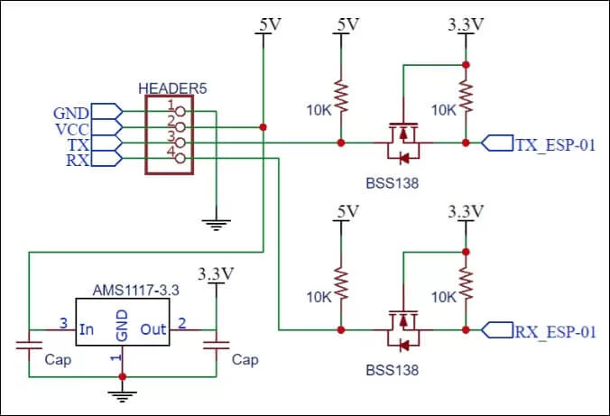
A good ESP-01 adapter that can satisfy the requirements for interfacing with Arduino boards is shown in Figure 6. It has a built-in 3.3V regulator and two (2) bi-directional logic level converters for the RX and TX pins. The schematic diagram for the adapter is shown in Figure 7.
ESP-01 Programmers
ESP-01 USB-to-Serial Converter Programmer Module
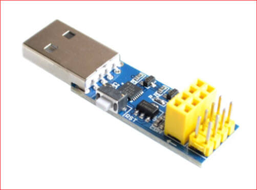
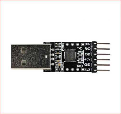
Unlike the other ESP8266 boards, ESP-01 boards need a programmer to be uploaded with programs or sketches from the Arduino IDE. An inexpensive programmer is shown below in Figure 8. The programmer uses a Silabs 2104 serial to USB converter chip. With this programmer, you just plug it into your computer’s USB port, select the proper COM port and start uploading sketches.
DIY USB-to-Serial Converter Programmer
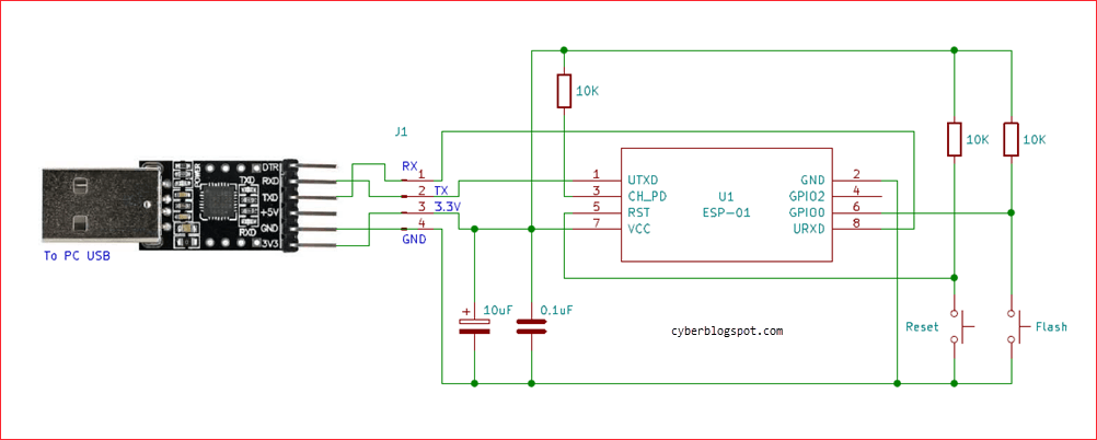
If you do not have a programmer module but you have an available USB-to-serial converter, you can wire it up as an ESP-01 programmer. The schematic diagram of a DIY programmer is shown in Figure 9. With this programmer, you need to put the ESP-01 module into programming mode before uploading a sketch. This is done by holding down the Flash switch, pressing and releasing the Reset switch, and then releasing the Flash switch.
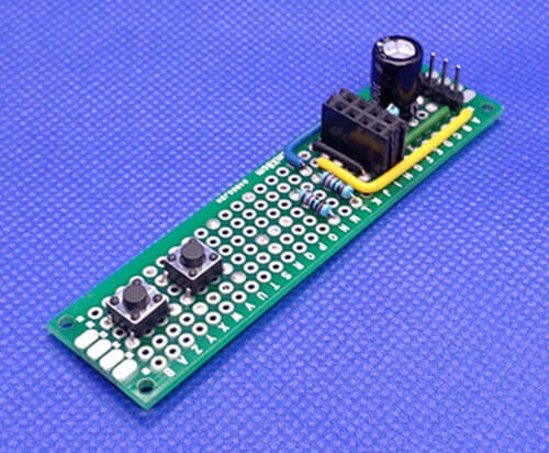
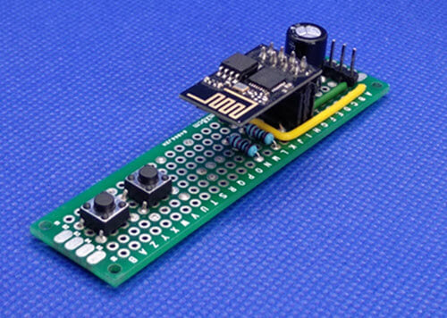
Shown below in Figures 10, 11, and 12 is my DIY ESP-01 programmer. The USB-to-serial converter connects to the programmer board via the 4-pin male header on the board.
Arduino Board as ESP-01 Programmer
Another option for an ESP-01 programmer is to use an Arduino board. You may use any available Arduino board such as Arduino Uno, Arduino Nano, etc.
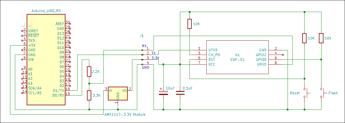
The idea here is to use the Arduino board’s built-in USB-to-serial converter. The schematic diagram in Figure 13 is the same as the DIY ESP-01 programmer in Figure 9, but the USB-to-serial converter was replaced with an Arduino Uno.
As previously discussed above, the 3.3V output from the Arduino board should not be used. Instead, a 3.3V voltage regulator was provided for the ESP-01 module. Also, a logic level converter was used consisting of a 2.2K resistor in series with a 3.3K resistor acting as a voltage divider. This protects the RX pin of the ESP-01 module from being exposed to a 5V signal from the Arduino board. Note that the TX pin of the ESP-01 module was connected directly to the TX pin of the Arduino board. We can do away with the logic level converter because the TX pin is acting as an output (outgoing signal).
You may have noticed that the TX and RX pins of the Arduino board are connected to the corresponding TX and RX pins of the ESP-01 module. But in the DIY programmer in Figure 9, the TX and RX terminals are cross-wired. That is, the TX pin of the USB-to-serial converter is connected to the RX pin of the ESP-01 module and ,vice versa, the RX pin of the USB-to-serial converter is connected to the TX pin of the ESP-01 module.
If you want to find out why the Arduino board’s RX and TX pins are wired straight thru and not crossed over with the ESP-01 board, consult an Arduino board schematic and look at how the MCU chip and the USB-to-serial converter chip are wired. I am leaving this one as an exercise for the reader.
Related Articles on ESP-01 and ESP-01S Pinout and Configuration
How to Program ESP-01 with Arduino IDE
How to Set up Arduino IDE for ESP8266 Programming
How to Test an ESP-01 ESP8266 Module
How to Control ESP-01 thru a Router
How to Control ESP-01 Without a Router
ESP-01 with RTC and LCD Display
How to Save and Restore ESP8266 and ESP32 Firmware
NodeMCU V3 ESP8266 Pinout and Configuration
How to Test a NodeMCU V3 ESP8266 Dev Board
How to Use AT-09 BLE with Arduino and Smartphone
References on ESP-01 and ESP-01S Pinout and Configuration
ESP-01 Specification
ESP-01 Datasheet