Circuit diagrams for the Honda Civic 2006 security system. The diagrams are applicable to Honda Civic FD (Eight Generation). That is, Honda Civic model year 2006-2011. The diagrams include the Keyless Entry System, the Power Door Locks, and the Security System with its Immobilizer System. These diagrams should facilitate understanding and troubleshooting of problems with the above-mentioned systems. Also, these diagrams are of great help if you intend to install or troubleshoot an installed aftermarket alarm system.
The heart of the system here is the MICU (Multiplex Integrated Control Unit). The MICU is located under the dashboard fuse/relay box. As can be seen from the diagrams, the MICU receives its inputs from different switches. It then drives several relays to activate the door actuators. Additionally, it controls the hazard lights (left turn and right turn signal lights) and the security horn.
Main Article: Honda Civic Wiring Diagram

Other Honda Civic Wiring Diagram
Honda Civic Audio System Wiring Diagram – Audio Unit, Speaker System, Antenna Module, Radio Remote Switch, Cassette Player Unit, and the Auxiliary Jack Assembly
Honda Civic Brake Lights Wiring Diagram – Left Brake Light, Right Brake Light and Brake Pedal Position Switch
Honda Civic Climate Control Wiring Diagram – Cruise Control, HVAC (Heating, Ventilation, and Air Conditioning), Climate Control, and Rear Window Defogger
Honda Civic Exterior Lights Wiring Diagram – Headlights, Position Lights, Tail Lights, and License Plate Light
Honda Civic Gauge Control Wiring Diagram – Dash Lights Brightness Control, the A/T (Automatic Transmission) Gear Position Indicator, and the Gauge Control Module (Speedo)
Honda Civic Interior Lights Wiring Diagram – Ambient Light, Ceiling Light, Courtesy Lights, Glove Box Light, Map Light, Trunk Light and the Vanity Mirror Lights
Honda Civic Power Windows Wiring Diagram – Power Window Master Switch, Driver’s Window Control Unit, Front Passenger’s Window Switch, Left Rear Window Switch, Right Rear Window Switch, and their corresponding Window Motors
Honda Civic Turn Signal/Hazard Flasher Circuit Diagram – Turn Signal Lights and Hazard Flasher Circuit Diagram
Honda Civic Windshield Wiper Wiring Diagram – MICU, Combination Light Switch, Turn Signal Switch, Hazard Warning Switch, Fog Light Switch, Windshield Wiper, Windshield Washer, and Headlight Washer
Honda Civic 2006 Security System Power Source
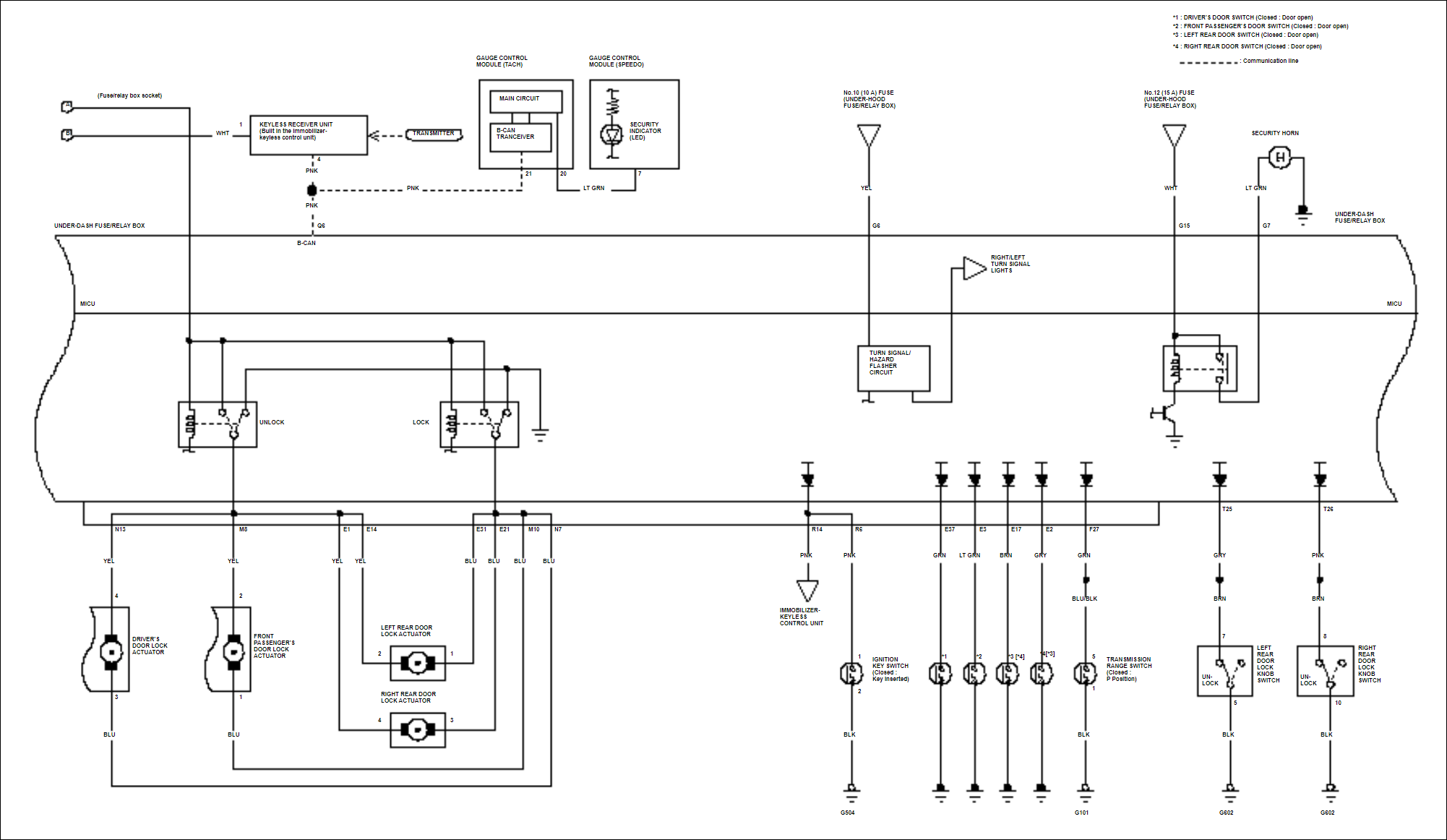
Figure 1 details how the MICU receives power from the battery. The whole MICU is powered from the battery thru a 100A fuse (No. 1). From the 100A fuse, a 50A fuse powers the MICU by passing thru the ignition switch. Two sets of fuses provide continuous, unswitched power to two separate circuits. One of them, the 40A fuse (No. 4) in series with a 20A fuse (No. 25) provides power to the Lock and Unlock relays and its accompanying door actuators. The second one, a 10A fuse (No. 23) powers the Keyless Receiver Unit.
Power Door Locks (a.k.a. Central Locking System)
Figure 1 also shows how the power door lock switches are wired. There are six switches that control the door lock actuators. Four of them are shown in Figure 1 and the other two (2) are located in Figure 2. The six switches are
- Driver’s Door Lock Switch
- Driver’s Door Key Cylinder Switch
- Driver’s Door Lock Knob Switch
- Front Passenger’s Lock Knob Switch
- Left Rear Lock Knob Switch
- Right Rear Lock Know Switch
When installing an aftermarket car alarm system on a Honda Civic, the alarm’s central locking system is tapped (connected) on the Driver’s Door Lock Switch. Connect the aftermarket alarm’s Lock wire the BLU wire and the Lock wire to the GRY wire.
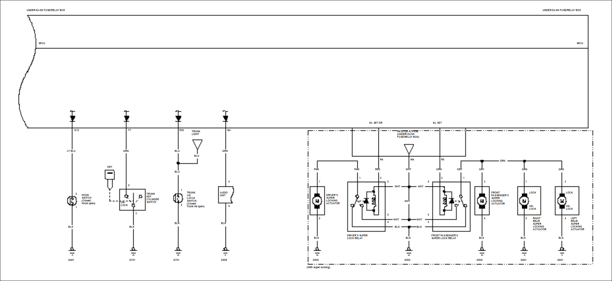
The four (4) door lock actuators that are controlled by these six (6) switches are shown in Figure 2. There is one door lock actuator for each of the four (4) doors: the driver’s door, front passenger’s door, left rear door, and the right rear door.
Keyless Entry System
In Figure 2, we can see the diagram for the Keyless Receiver Unit. This unit is responsible for receiving the Lock and Unlock signals from the fob key remote controller. The remote controller locks or unlocks the door wirelessly. At the same time, it either arms or disarms the security alarm system.
Security Alarm System
Another system in Figure 2 above is the security alarm system. It shows that the MICU controls the hazard lights (turn signal lights) and the security horn. If the car model has the super-locking feature, it includes another set of four (4) door lock actuators. This is detailed in Figure 3 below (inside the dotted rectangle).
References for Honda Civic 2006 Security System Diagrams
https://en.wikipedia.org/wiki/Honda_Civic_(eighth_generation) – Information on one of the best-selling cars in world, the Honda Civic Eight Generation.
Replace a Defective Key Fob for Six Dollars – Replace a defective key fob by installing a new central locking system that includes two (2) brand new key fobs.