A collection of Honda Civic 2006 wiring diagram. These diagrams may apply to Honda Civic FD also known as Eight Generation Honda Civic or Honda Civic model years 2006-2011.
For more detailed Honda Civic wiring diagrams with functional descriptions, please visit Honda Civic Wiring Diagram
- Figure 1 – Battery, Starting System, Charging System, and Ignition System
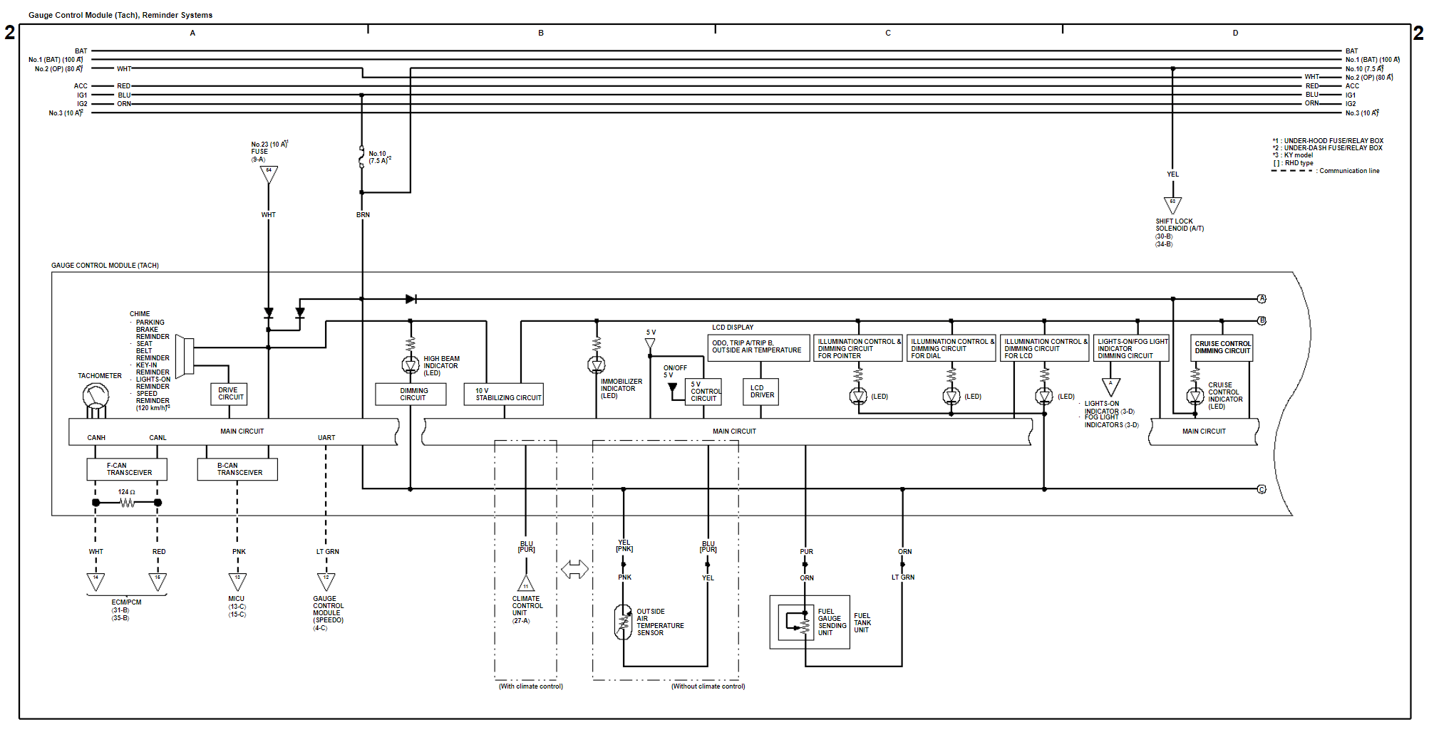
- Figure 2 – Gauge Control Module (Tach), and Reminder System
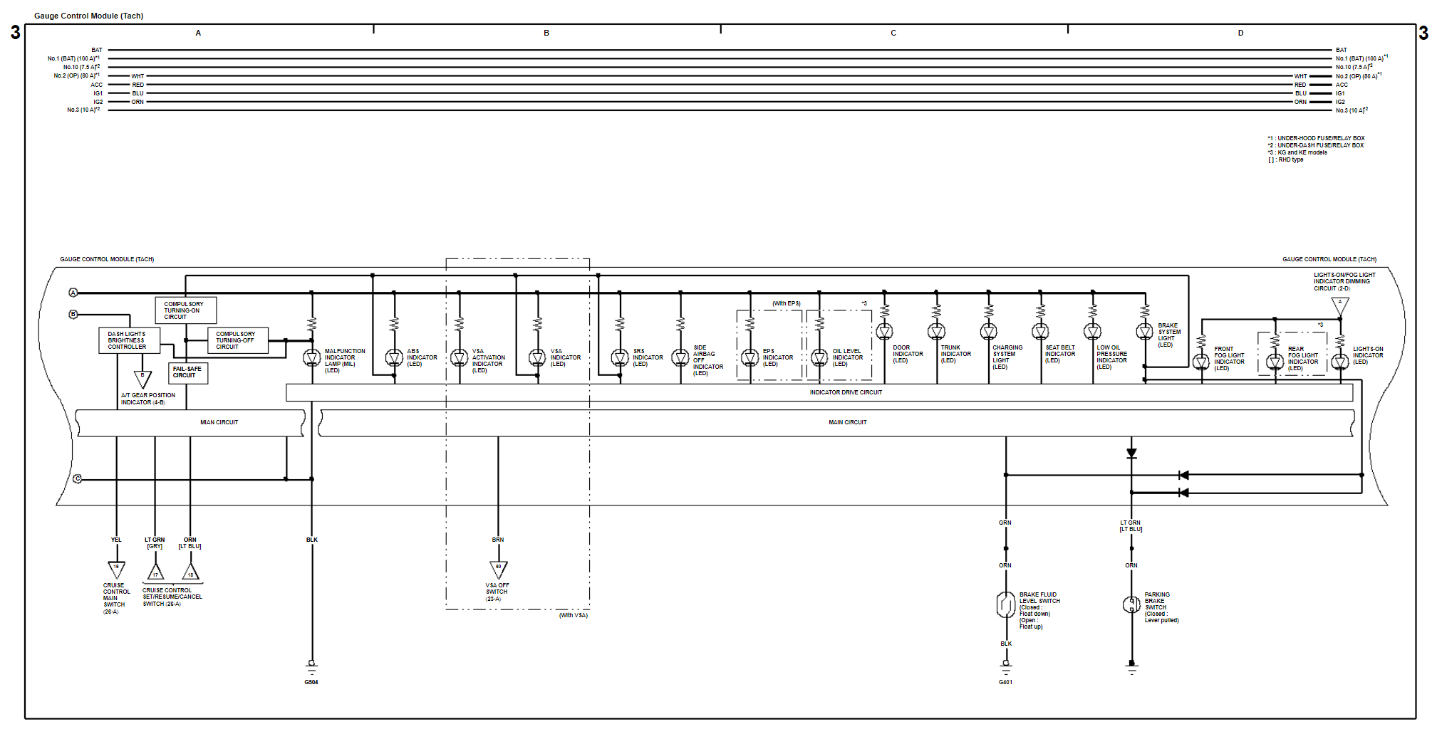
- Figure 3 – Gauge Control Module (Tach)
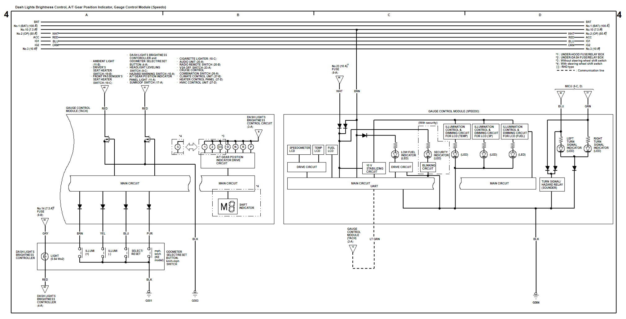
- Figure 4 – Dash Lights Brightness Control, A/T (Automatic Transmission) Gear Position Indicator, and Gauge Control Module (Speedo)
- Figure 5 – Exterior Lights with HID (High Intensity Discharge)
- Figure 6 – Exterior Lights without HID (High Intensity Discharge)
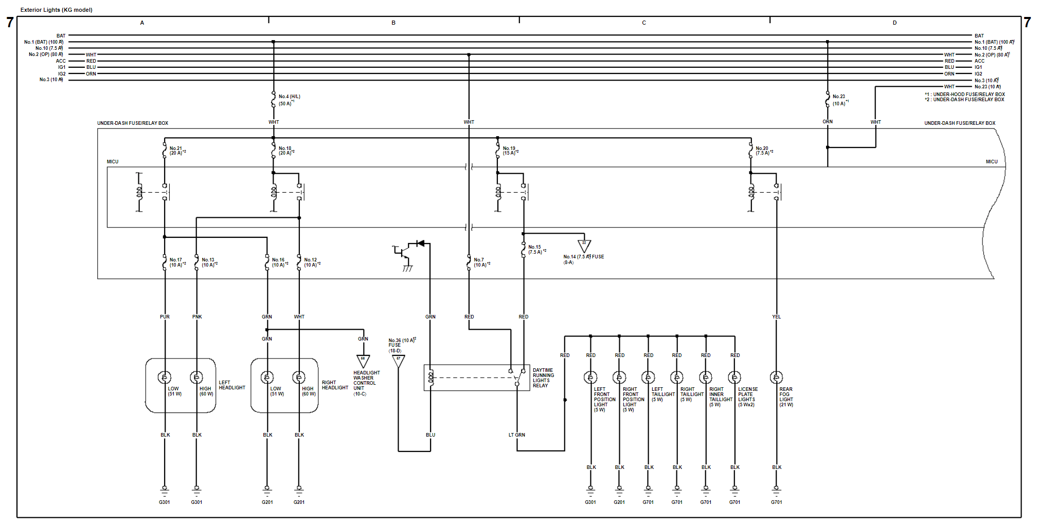
- Figure 7 – Exterior Lights (KG Models)
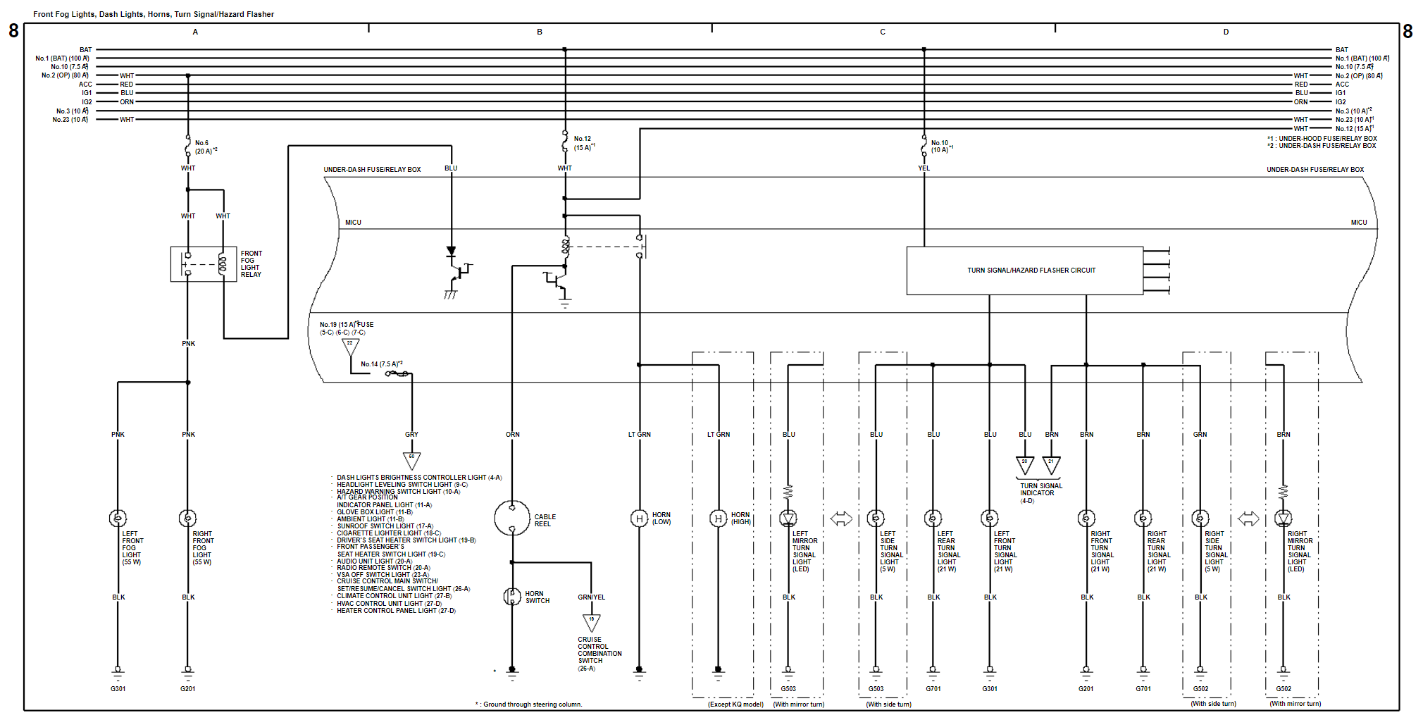
- Figure 8 – Front Fog Lights, Dash Lights, Horns, Turn Signal and Hazard Flasher
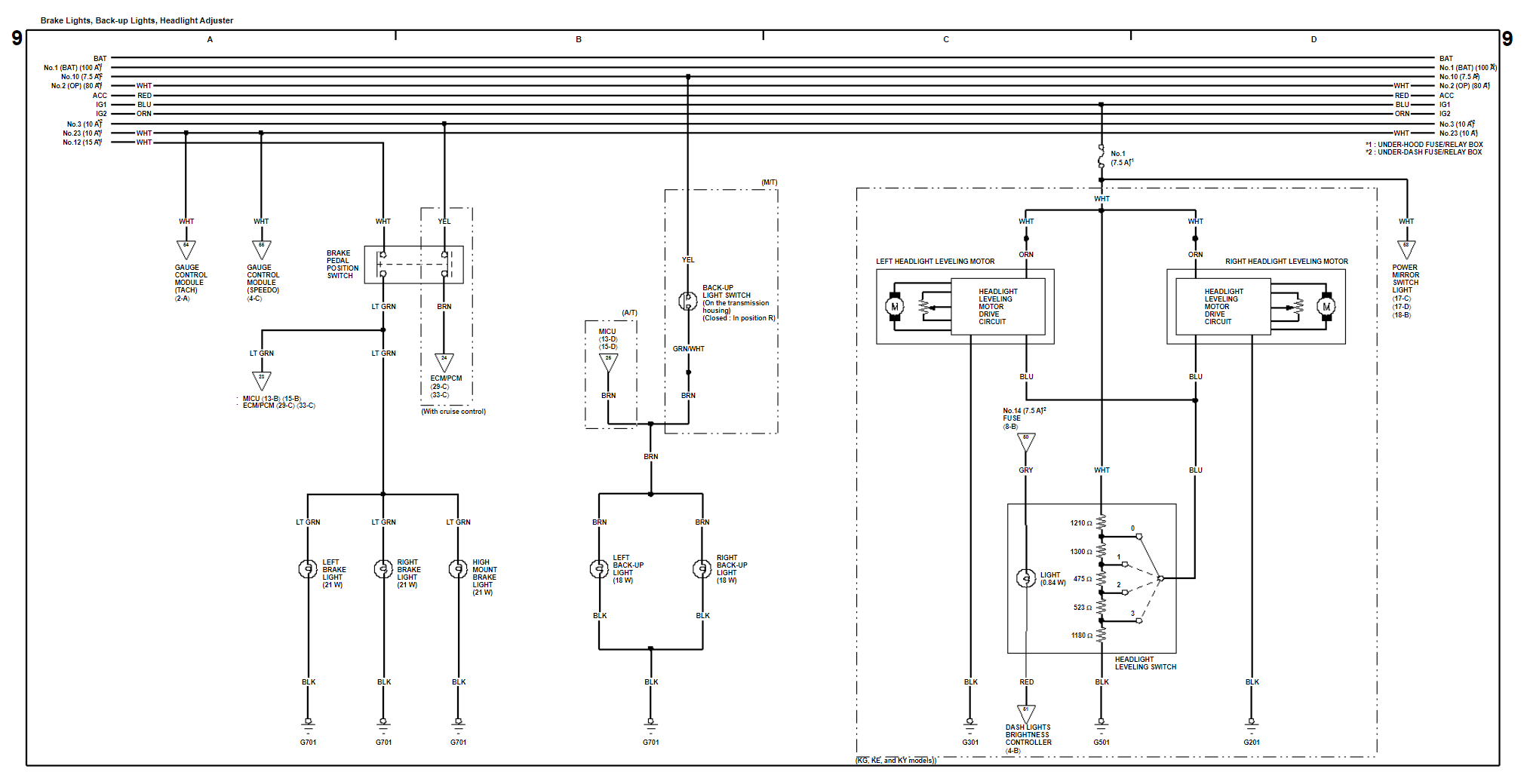
- Figure 9 – Brake Lights, Back-up Lights, and Headlight Adjuster
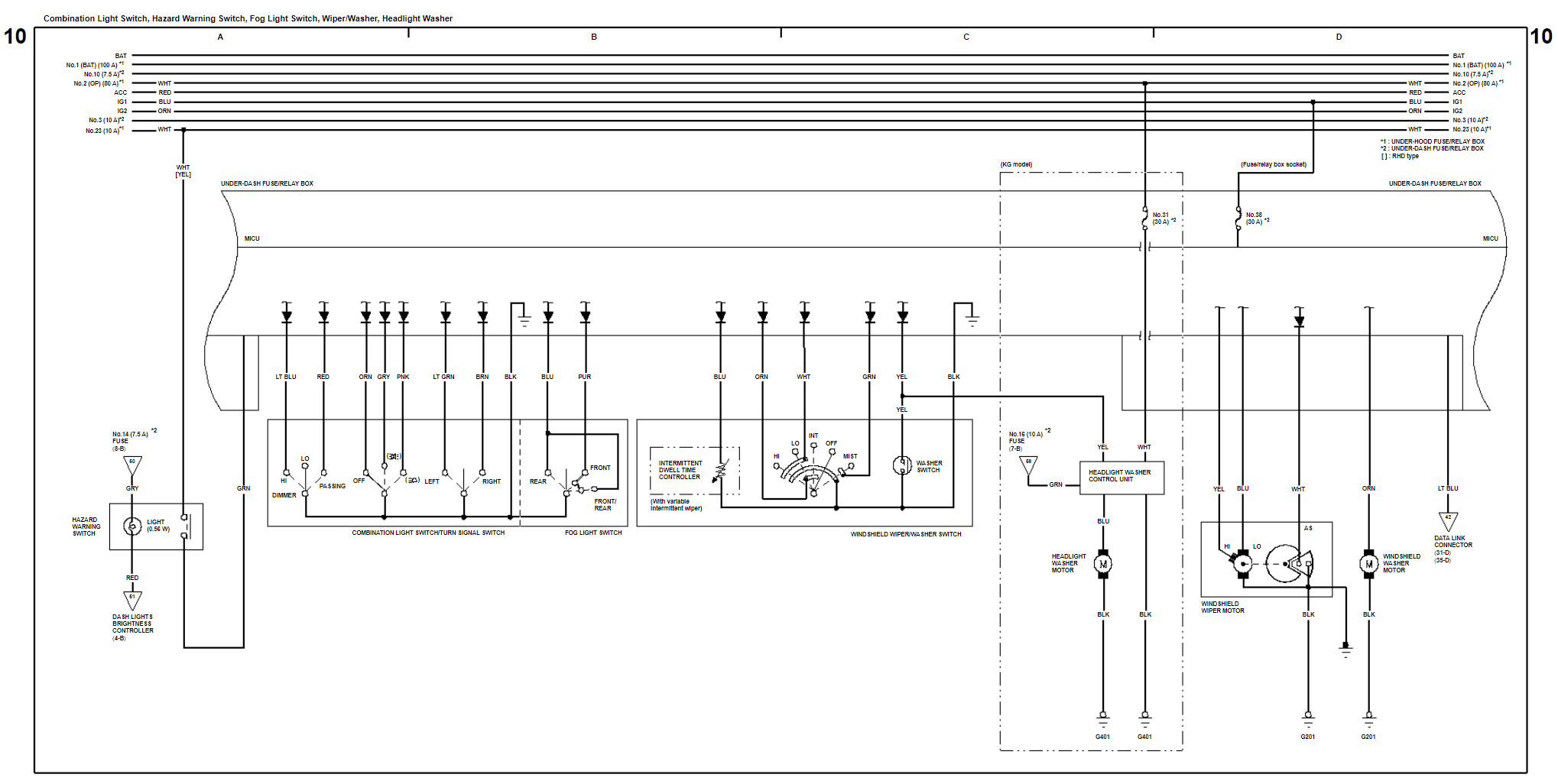
- Figure 10 – Combination Light Switch, Hazard Warning Switch, Fog Light Switch, Windshield Wiper, Windshield Washer, and Headlight Washer
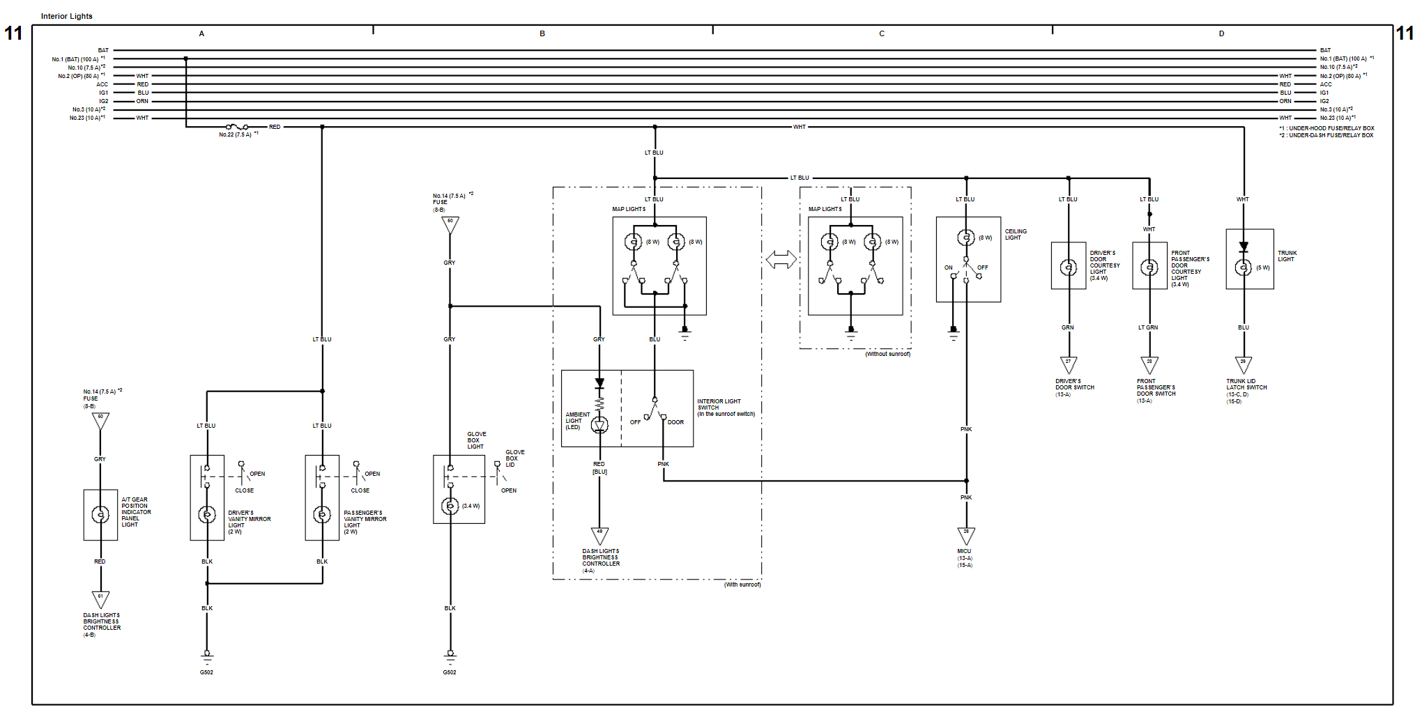
- Figure 11 – Ambient Light, Ceiling Light, Courtesy Lights, Glove Box Light, Map Light, Trunk Light and Vanity Mirror Lights
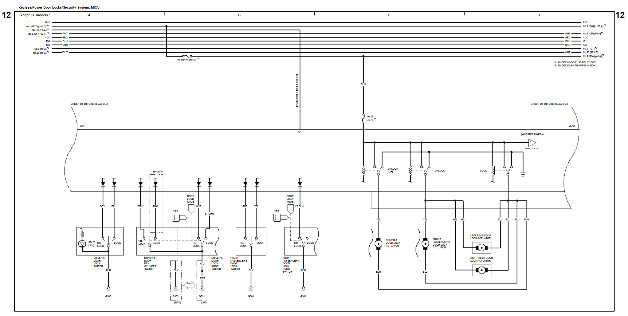
- Figure 12 – Keyless Entry System (Central Locking System), Power Door Locks System, Security System (Alarm System), and MICU – EXCEPT KE MODELS
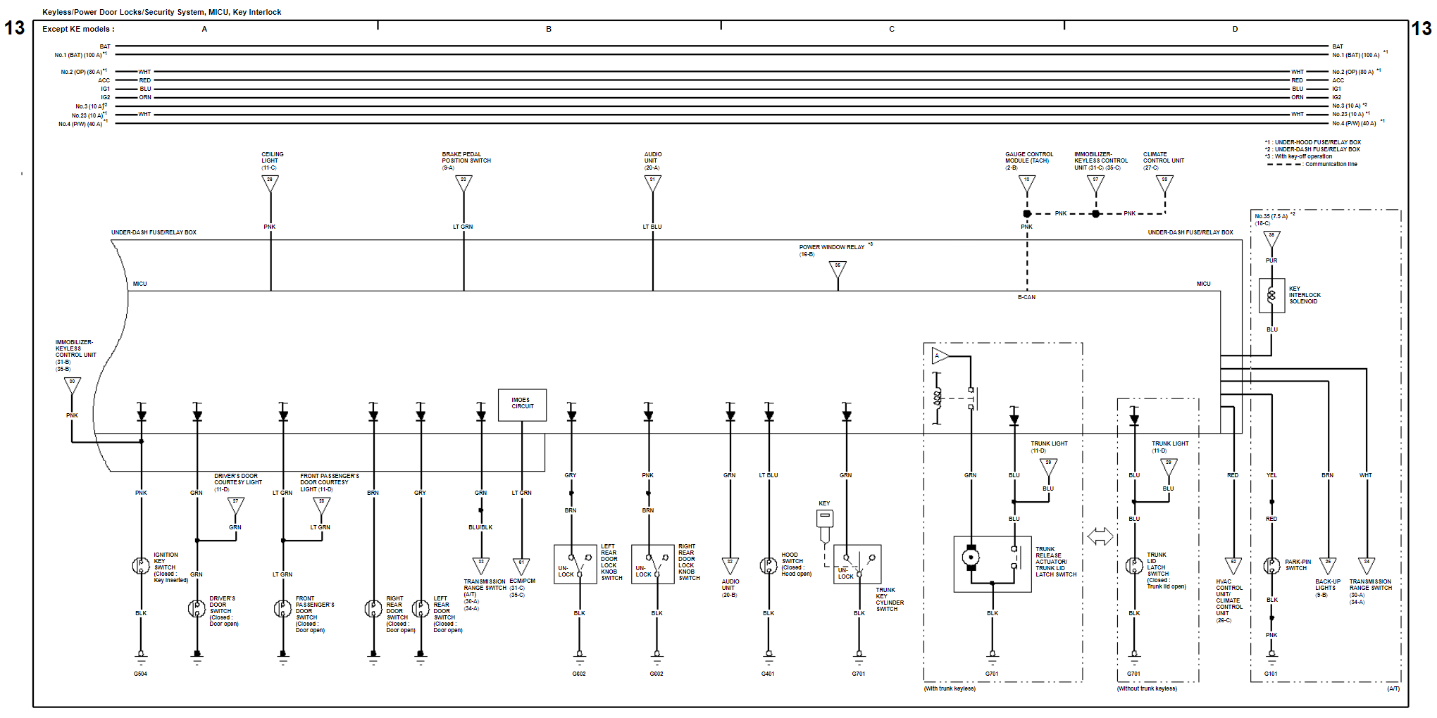
- Figure 13 – Keyless Entry System (Central Locking System), Power Door Locks System, Security System (Alarm System), MICU and Key Interlock – EXCEPT KE MODELS
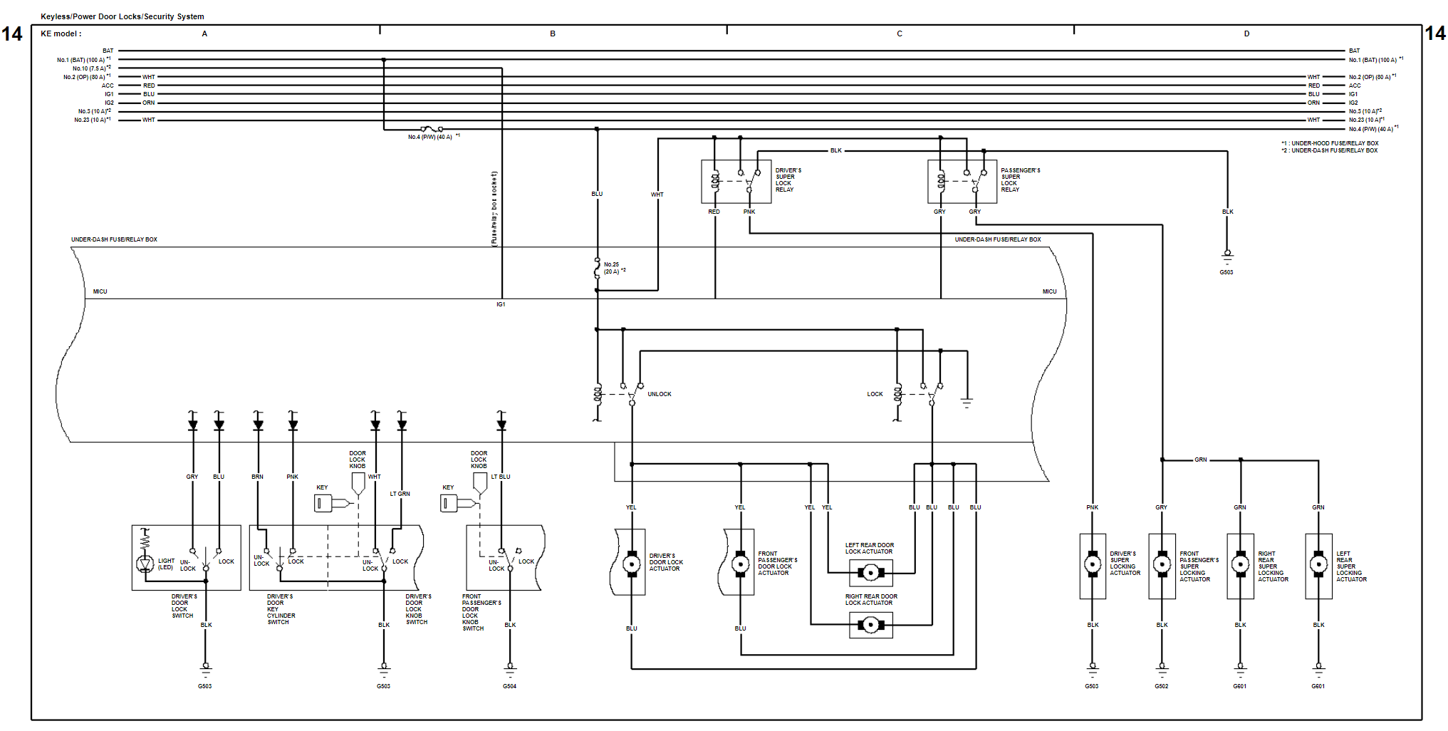
- Figure 14 – Keyless Entry System (Central Locking System), Power Door Locks System, Security System (Alarm System), and MICU – KE MODELS
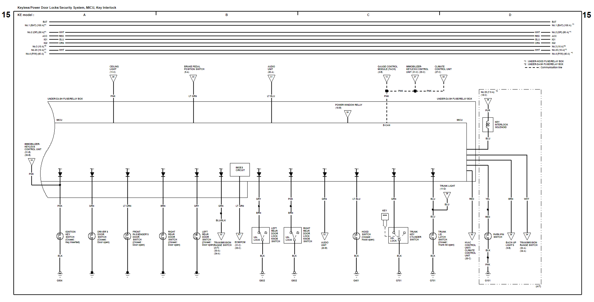
- Figure 15 – Keyless Entry System (Central Locking System), Power Door Locks System, Security System (Alarm System), MICU and Key Interlock – KE MODELS
- Figure 16 – Power Window Master Switch, Driver’s Window Control Unit, Front Passenger’s Window Switch, Left Rear Window Switch, Right Rear Window
- Figure 17 – Sunroof Control Unit and Power Mirrors
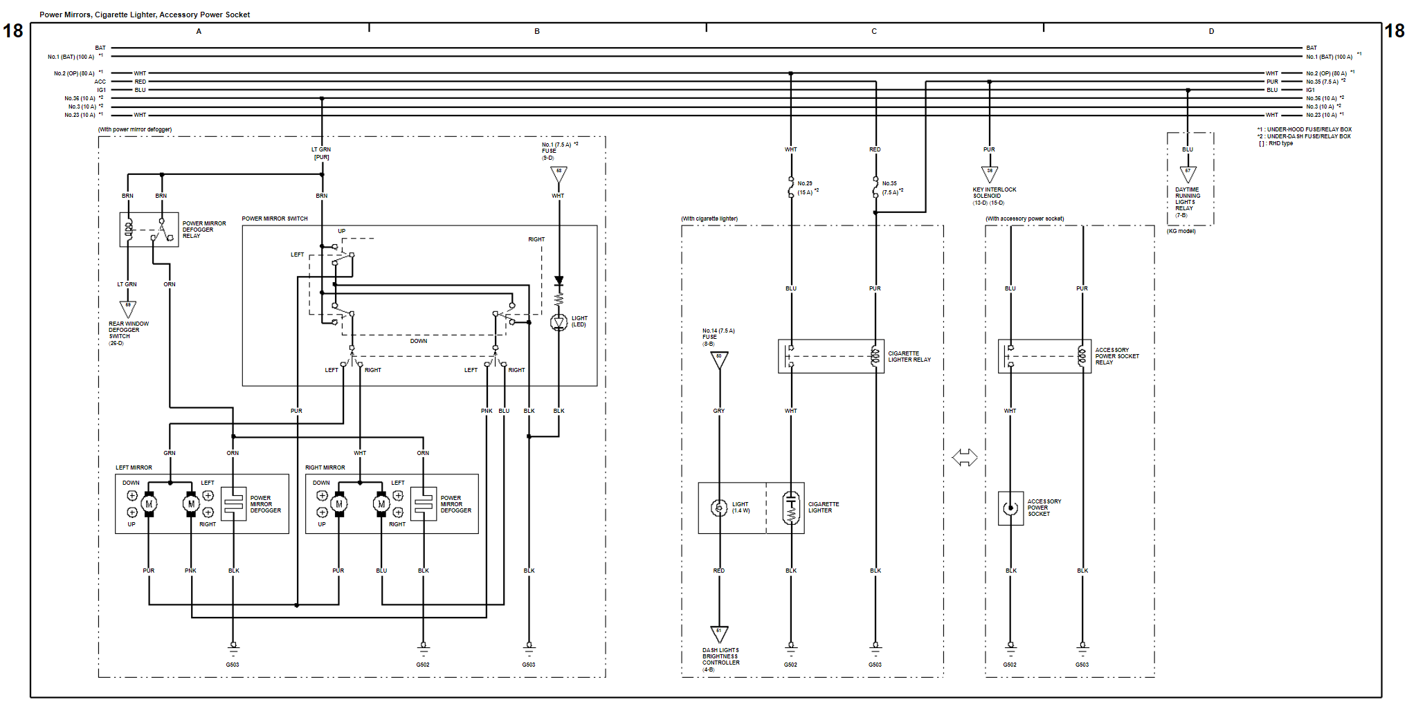
- Figure 18 – Power Mirrors, Cigarette Lighter, and Accessory Power Socket
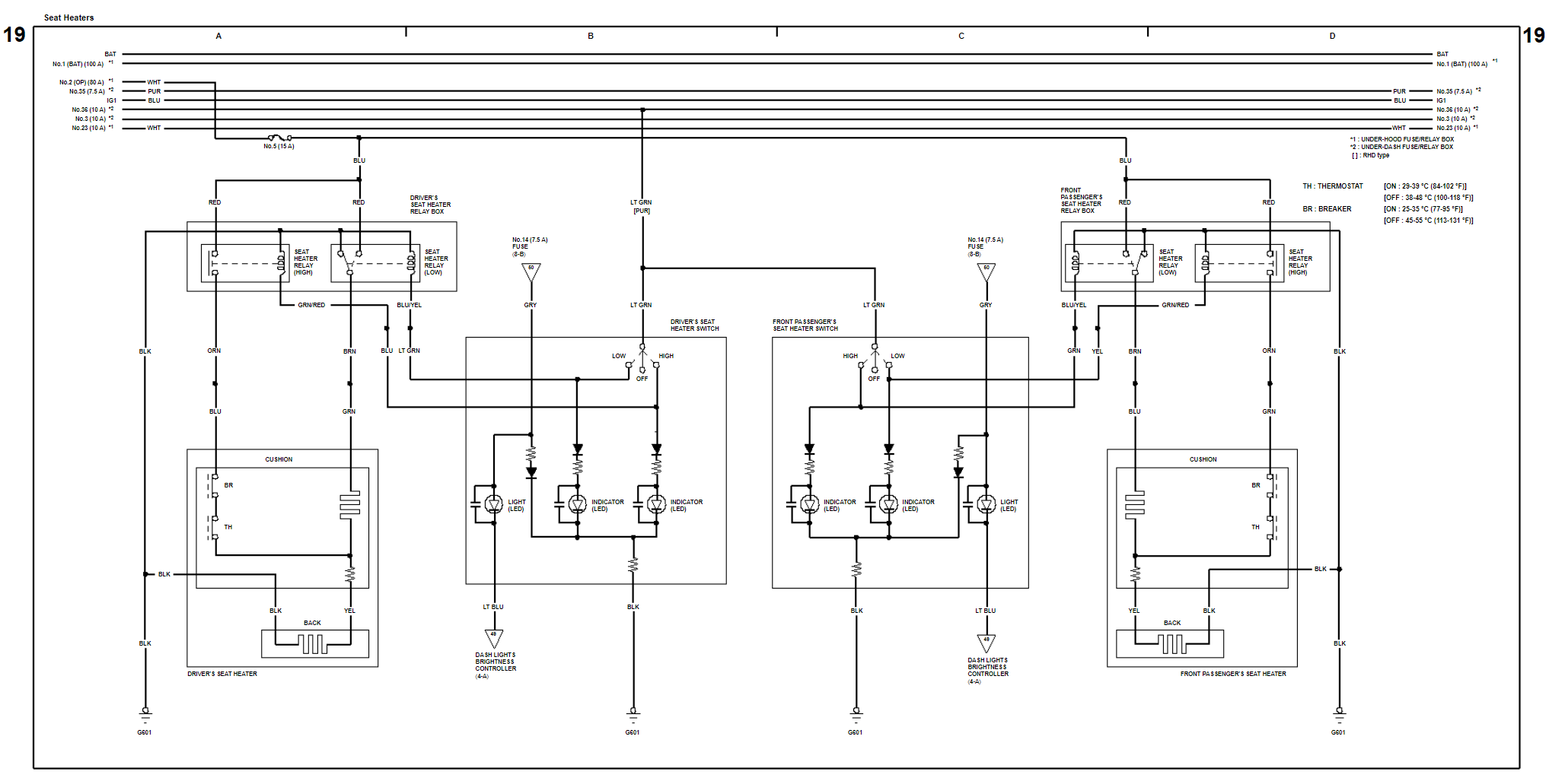
- Figure 19 – Seat Heaters and Seat Heater Relay Boxes
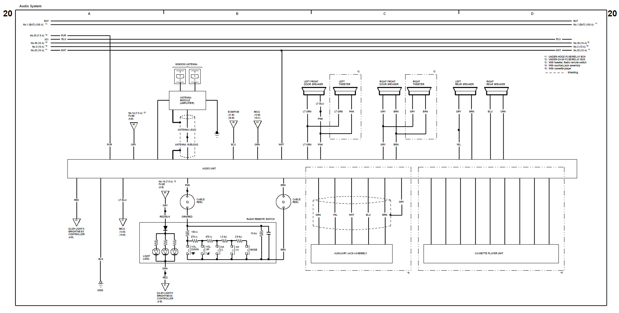
- Figure 20 – Audio Unit, Speaker System, Antenna Module, Radio Remote Switch, Cassette Player Unit, and the Auxiliary Jack Assembly
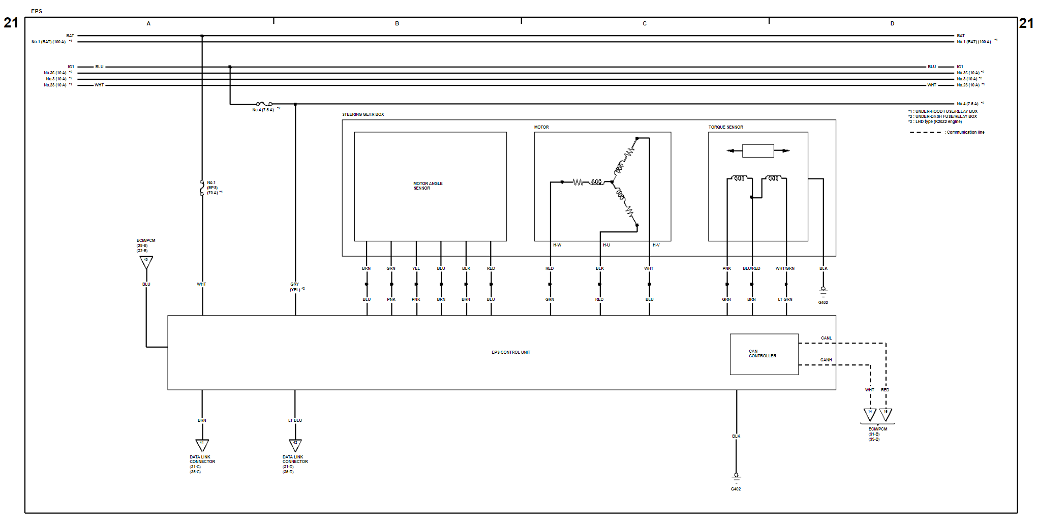
- Figure 21 – Electric Power Steering (EPS) Control Unit and Steering Gear Box
- Figure 22 – Anti-Lock Braking System (ABS) Modulator Control Unit
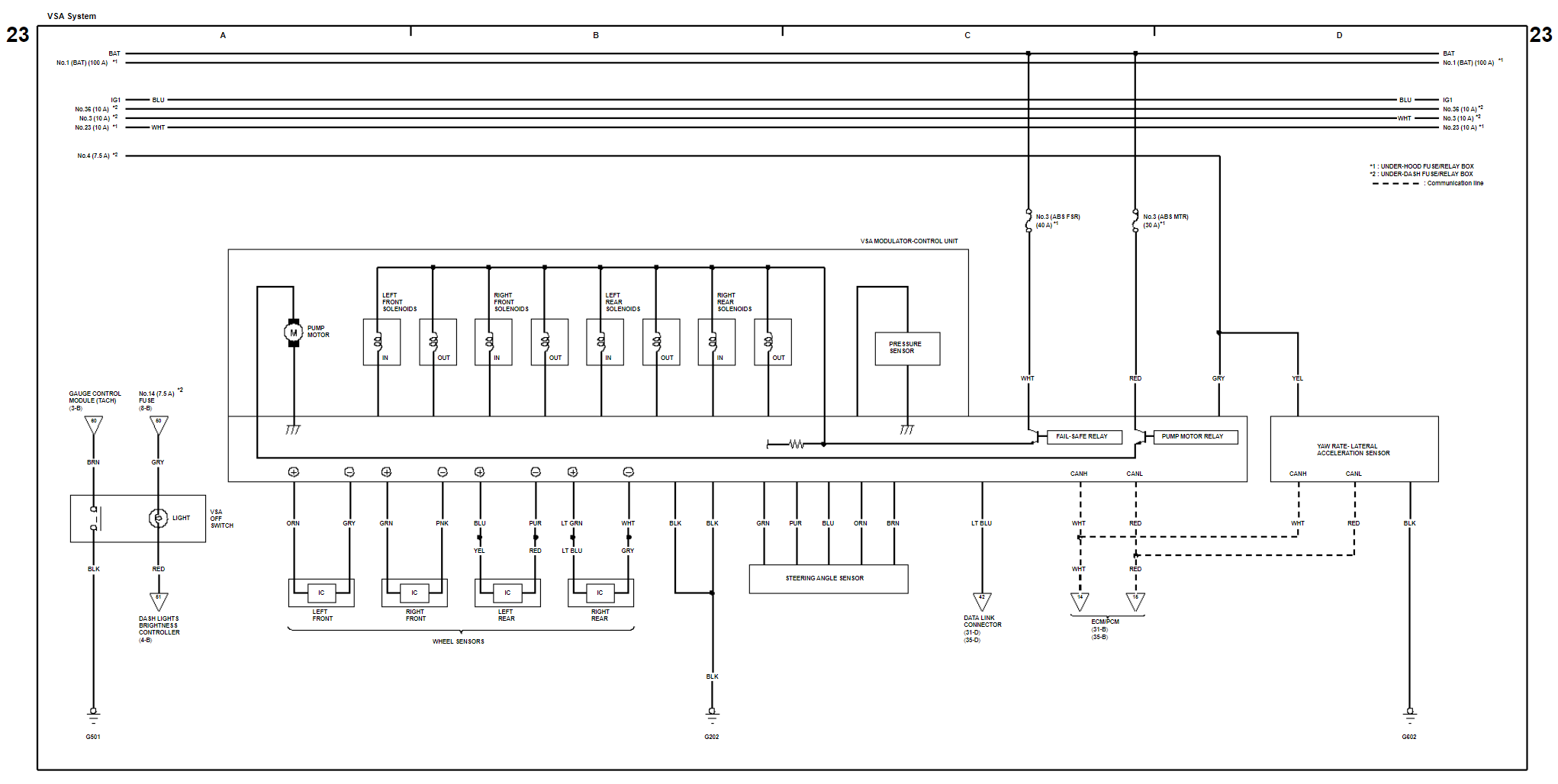
- Figure 23 – Vehicle Stability Assist (VSA) Modulator Control Unit
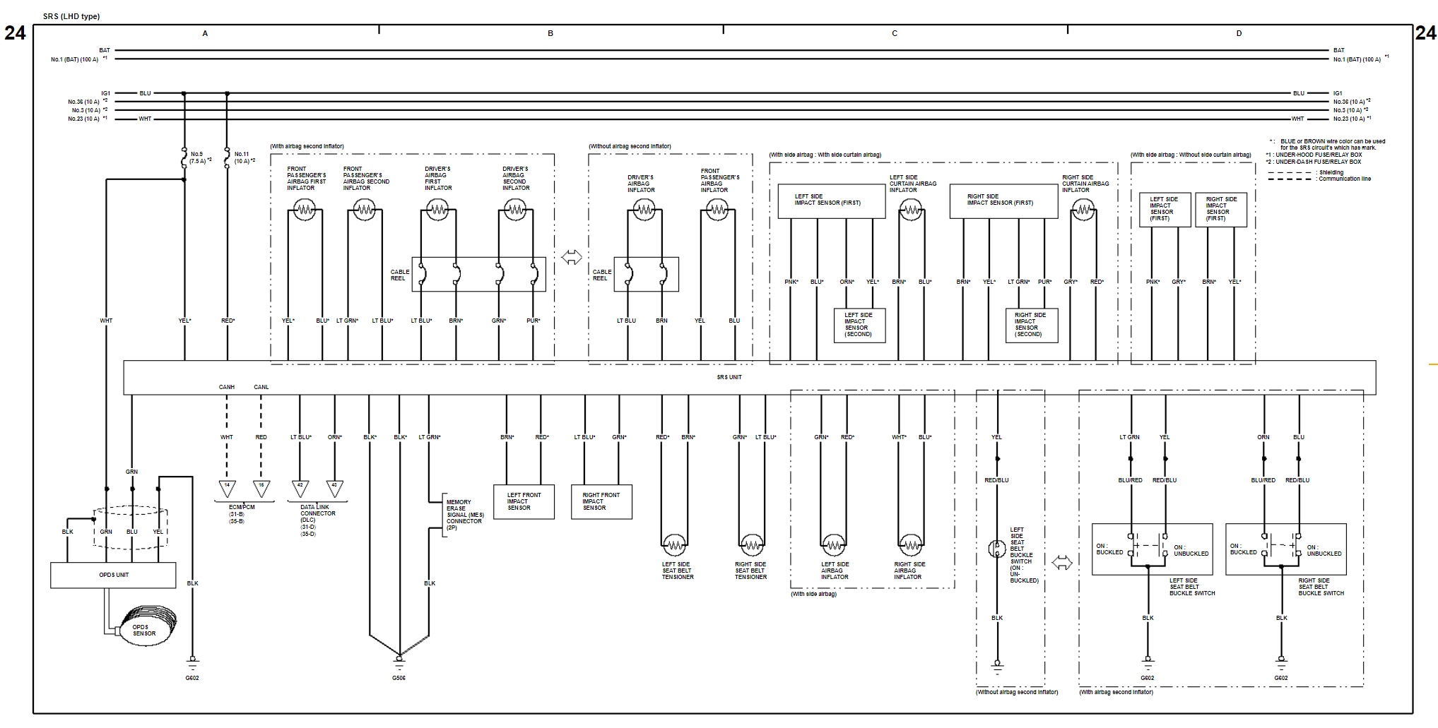
- Figure 24 – Supplemental Restraint System (SRS) (Airbags) LHD Type
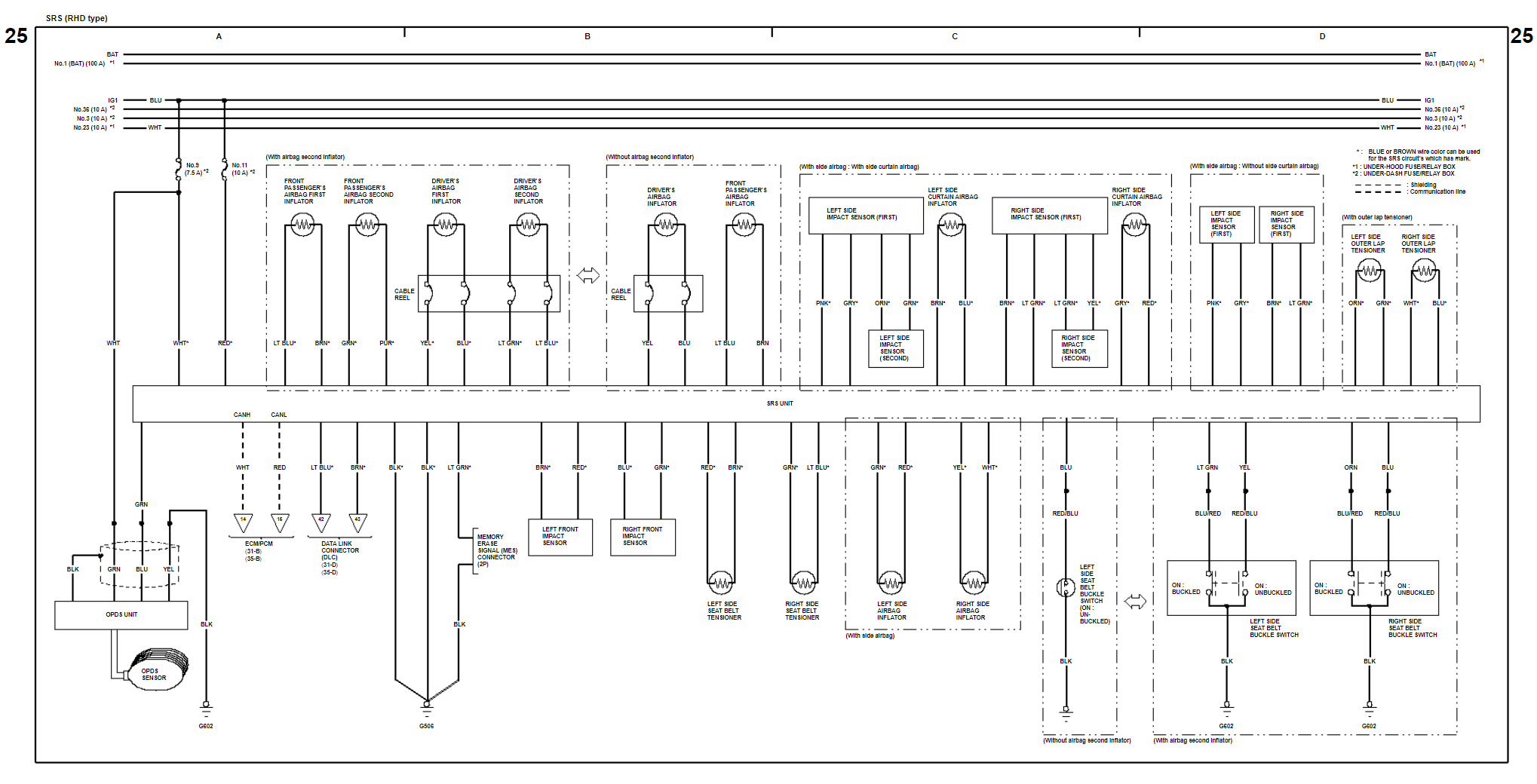
- Figure 25 – Supplemental Restraint System (SRS) (Airbags) RHD Type
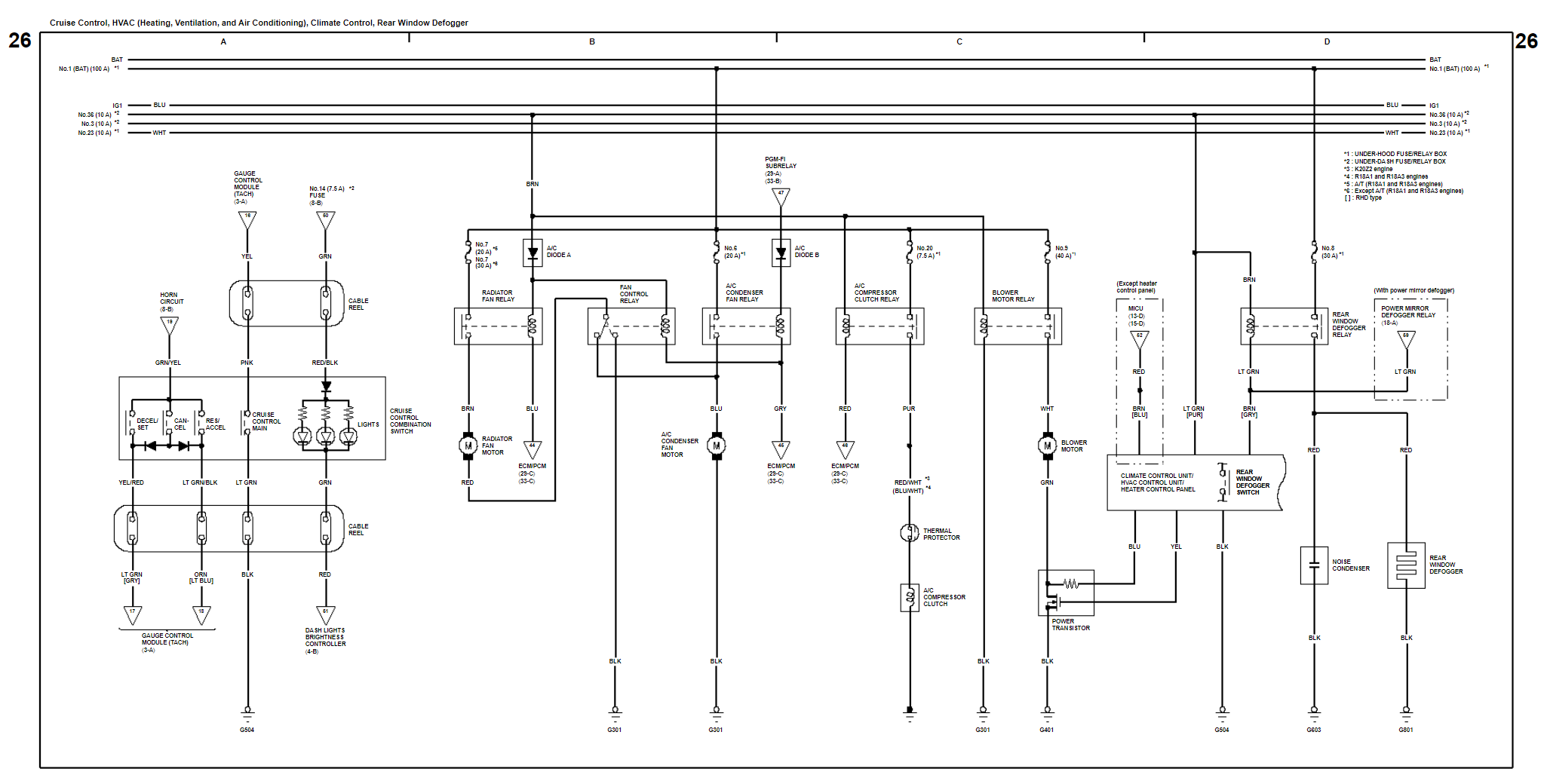
- Figure 26 – Cruise Control, HVAC (Heating, Ventilation, and Air Conditioning), Climate Control, and Rear Window Defogger
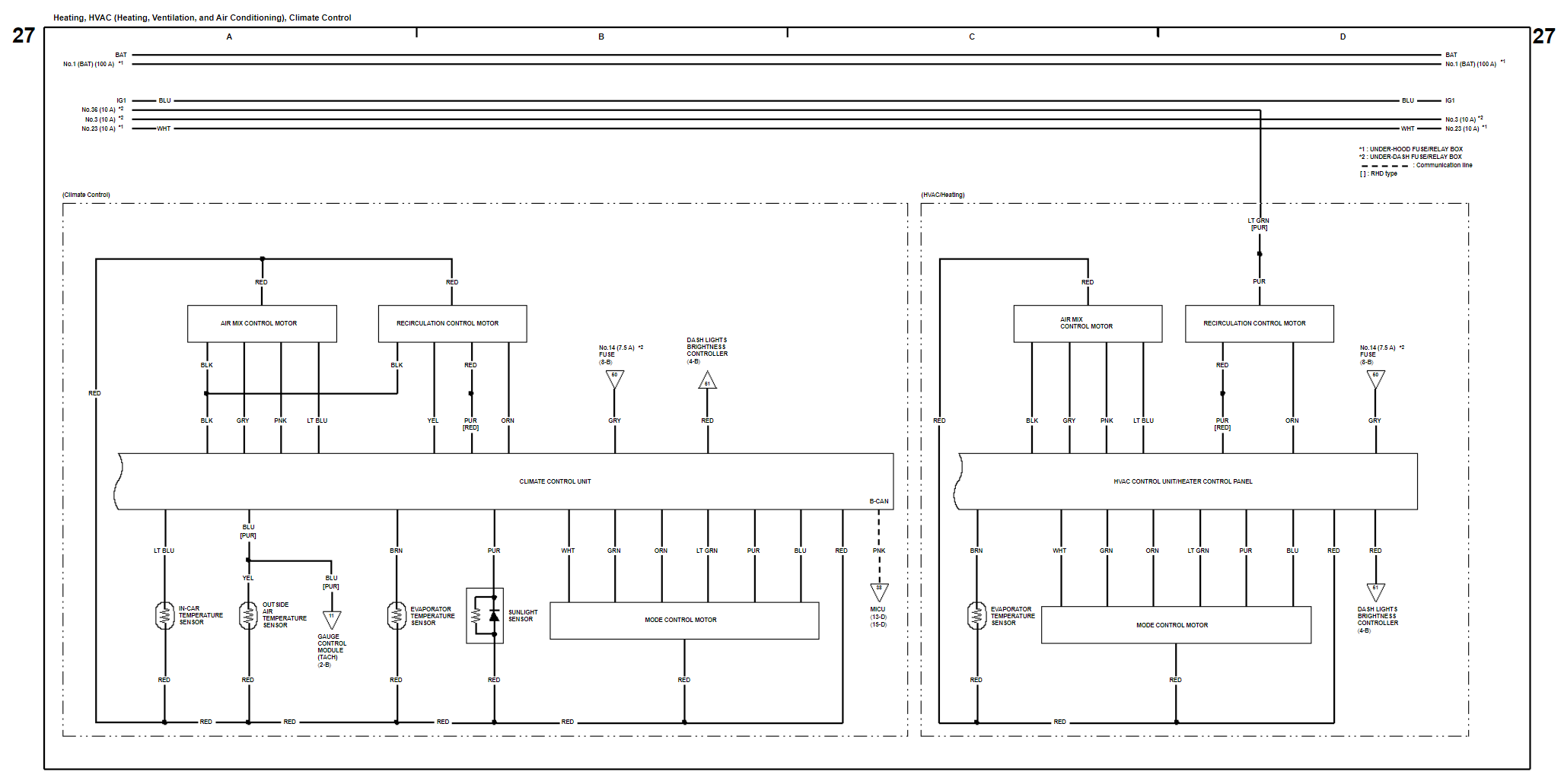
- Figure 27 – Heating, HVAC (Heating, Ventilation, and Air Conditioning), and Climate Control
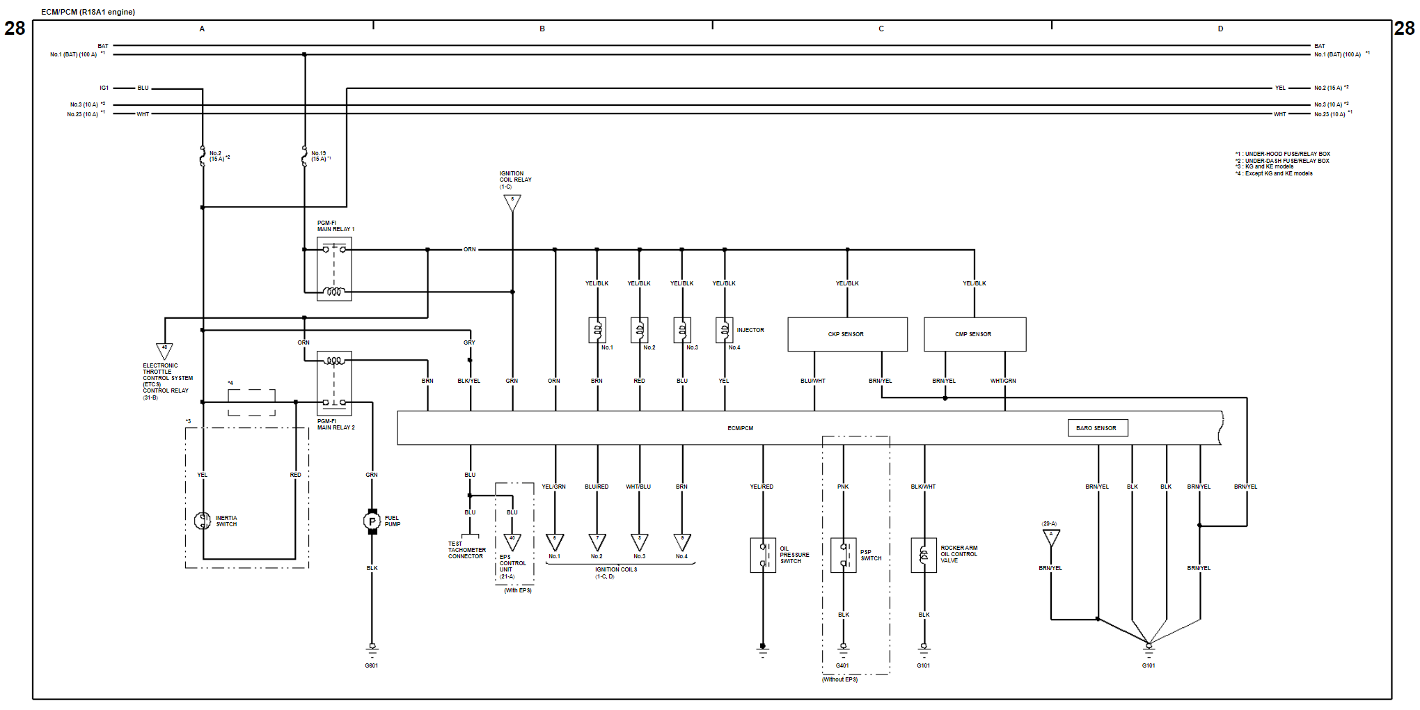
- Figure 28 – ECM/PCM (Engine Control Module/Powertrain Control Module) for R18A1 and R18A3 engines
- Figure 29 – ECM/PCM (Engine Control Module/Powertrain Control Module) for R18A1 and R18A3 engines
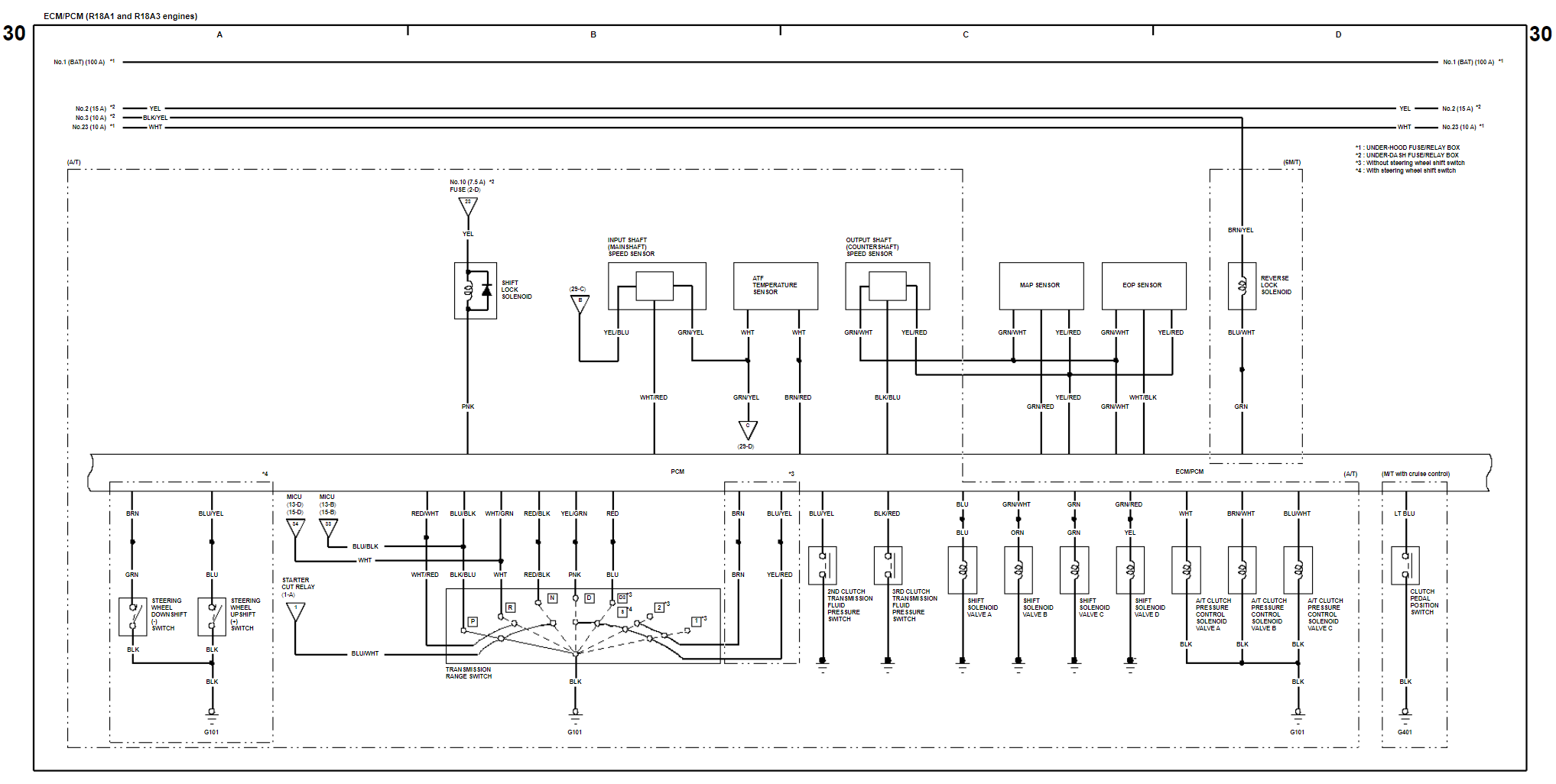
- Figure 30 – ECM/PCM (Engine Control Module/Powertrain Control Module) and Shift Lock (A/T) for R18A1 and R18A3 engines
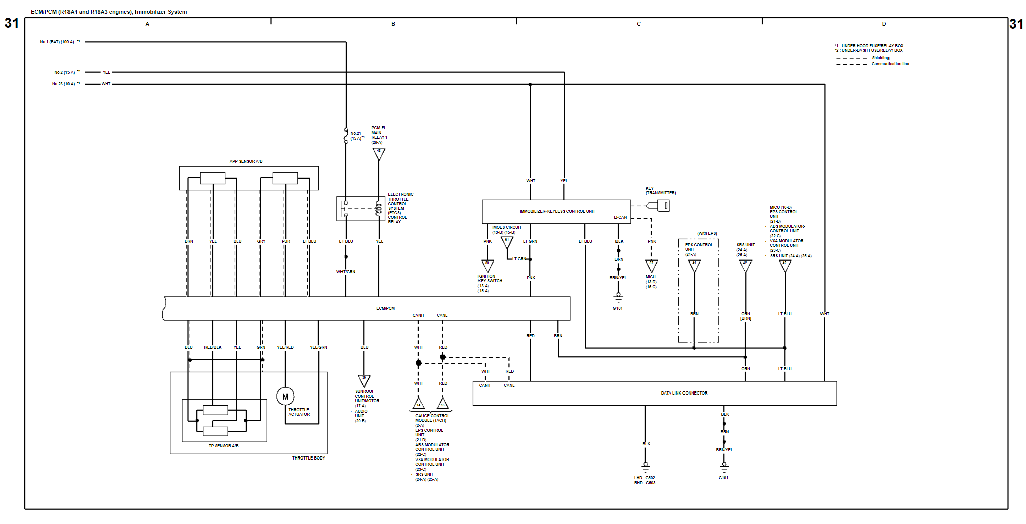
- Figure 31 – ECM/PCM (Engine Control Module/Powertrain Control Module), Immobilizer System, Keyless Receiver, and Key Interlock (Except KE) for R18A1 and R18A3 engines
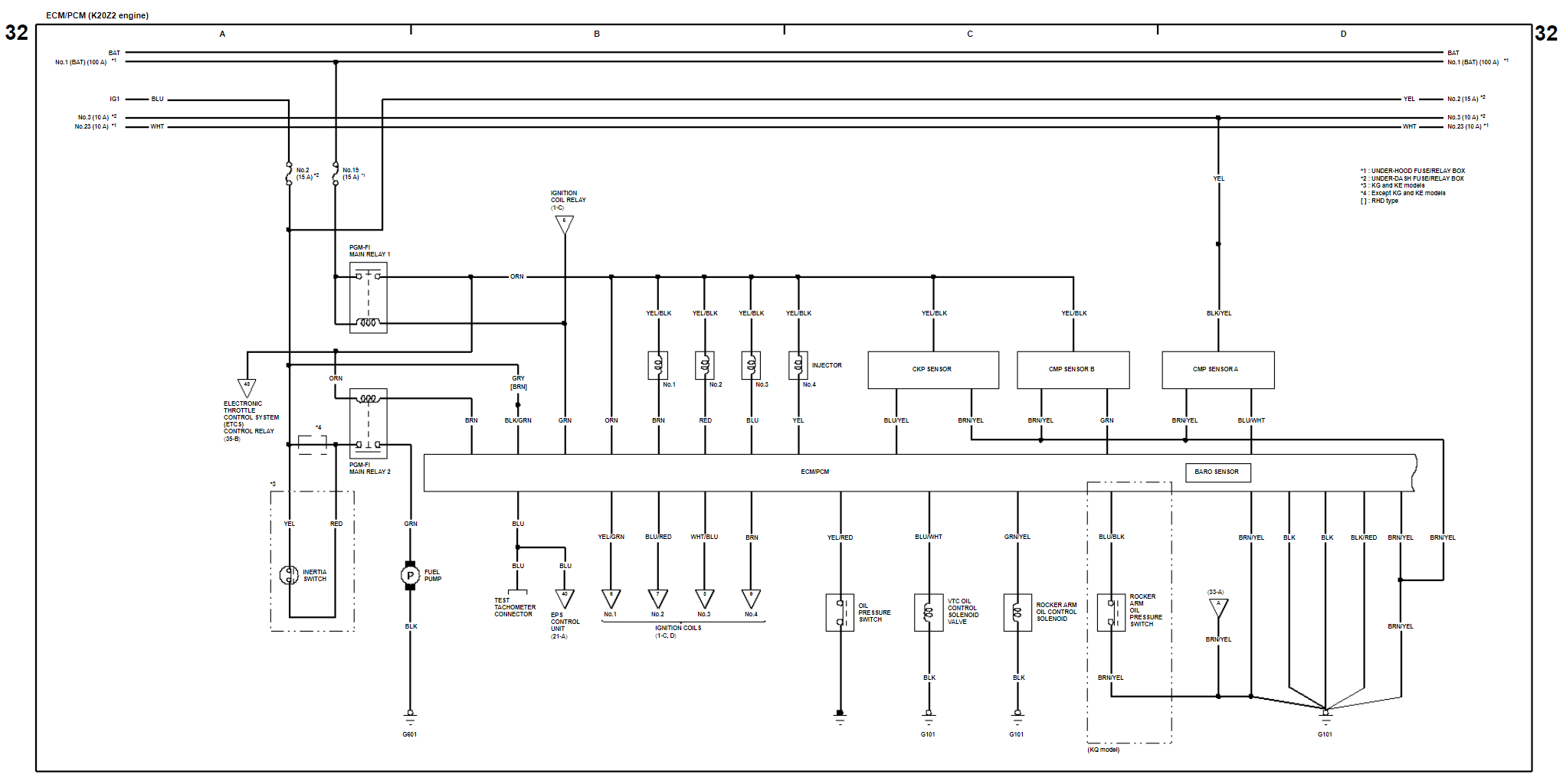
- Figure 32 – ECM/PCM (Engine Control Module/Powertrain Control Module) for K20Z2 engine
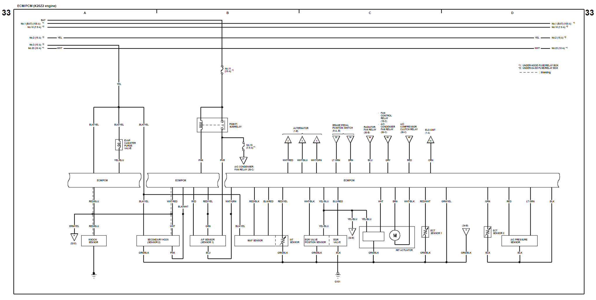
- Figure 33 – ECM/PCM (Engine Control Module/Powertrain Control Module) for K20Z2 engine
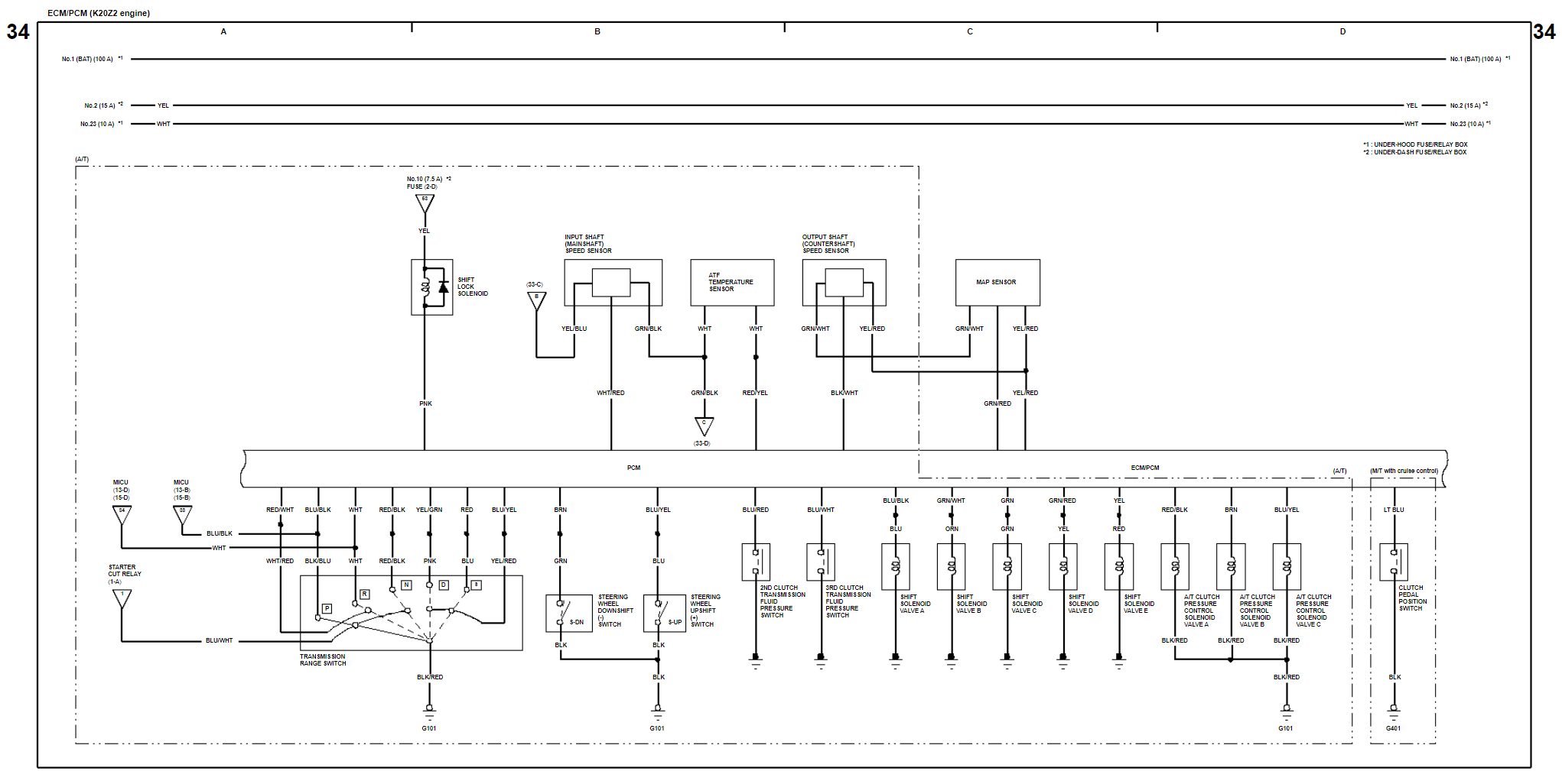
- Figure 34 – ECM/PCM (Engine Control Module/Powertrain Control Module) and Shift Lock (A/T) for K20Z2 engine
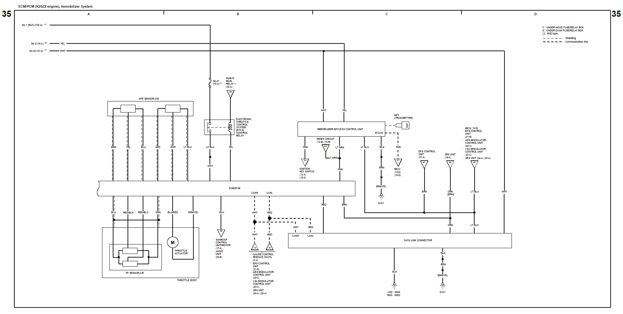
- Figure 35 – ECM/PCM (Engine Control Module/Powertrain Control Module), Immobilizer System, Keyless Receiver, and Key Interlock (Except KE) for K20Z2 engine


References on Honda Civic 2006 Wiring Diagram
https://en.wikipedia.org/wiki/Honda_Civic_(eighth_generation) – Information on one of the best-selling cars in world, the Honda Civic Eight Generation.
Replace a Defective Key Fob for Six Dollars – Replace a defective key fob by installing a new central locking system that includes two (2) brand new key fobs.