Honda Civic, one of the best-selling cars in world, is made by Honda Motor Co., Ltd., a Japanese manufacturer of automobiles, motorcycles, and power equipment like motors and pumps. The sets of Honda Civic wiring diagram presented here were taken from the Honda Civic 2006 Service Manual. As such, the wiring diagrams should be applicable to Honda Civic FD (Eighth Generation) or Honda Civic year models 2006-2011.

Source: Wikipedia

Source: Wikipedia
Available Honda Civic Wiring Diagram
Honda Civic Audio System Wiring Diagram – Audio Unit, Speaker System, Antenna Module, Radio Remote Switch, Cassette Player Unit, and the Auxiliary Jack Assembly
Honda Civic Brake Lights Wiring Diagram – Left Brake Light, Right Brake Light and Brake Pedal Position Switch
Honda Civic Climate Control Wiring Diagram – Cruise Control, HVAC (Heating, Ventilation, and Air Conditioning), Climate Control, and Rear Window Defogger
Honda Civic Exterior Lights Wiring Diagram – Headlights, Position Lights, Tail Lights, and License Plate Light
Honda Civic Gauge Control Wiring Diagram – Dash Lights Brightness Control, the A/T (Automatic Transmission) Gear Position Indicator, and the Gauge Control Module (Speedo)
Honda Civic Interior Lights Wiring Diagram – Ambient Light, Ceiling Light, Courtesy Lights, Glove Box Light, Map Light, Trunk Light and the Vanity Mirror Lights
Honda Civic Power Windows Wiring Diagram – Power Window Master Switch, Driver’s Window Control Unit, Front Passenger’s Window Switch, Left Rear Window Switch, Right Rear Window Switch, and their corresponding Window Motors
Honda Civic 2006 Security System Diagrams – Security Alarm System, Keyless Entry System (Central Locking System), and Power Door Locks System
Honda Civic Turn Signal/Hazard Flasher Circuit Diagram – Turn Signal Lights and Hazard Flasher Circuit Diagram
Honda Civic Windshield Wiper Wiring Diagram – MICU, Combination Light Switch, Turn Signal Switch, Hazard Warning Switch, Fog Light Switch, Windshield Wiper, Windshield Washer, and Headlight Washer
Starting System, Charging System, and Ignition System Wiring Diagram
The wiring diagram in Figure 1 shows the details of the starting system, charging system, and the ignition system. We are going to analyze and describe each of the system as we go on.
STARTING SYSTEM
The starting system is composed of the 12-V battery, the starter, the starter cut relay, and the ignition switch. The starter itself is composed of the starter motor and the solenoid. The solenoid is responsible for switching the high current required by the starter motor. You will notice that the starter motor is powered directly from the battery without any intervening fuses thru the solenoid switch controlled by the solenoid coil. The solenoid coil, in turn, is powered thru the ST terminal of the ignition switch and thru the starter cut relay. The starter cut relay is a safety interlock to prevent the starter from switching on when the transmission is not in the parked position.
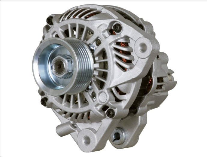
CHARGING SYSTEM
The alternator is responsible for charging the battery when the engine is running. The alternator is formed by the field coils, rectifier diodes, and a voltage regulator unit. When running, the field coils of the alternator produce an AC voltage that is fed to the rectifier. The rectifier converts the AC voltage into a DC voltage and sends it to the voltage regulator unit. The voltage regulator unit adjusts the output voltage depending on the power needs.
Also part of the charging system is the ELD or the Electronic Load Detector. The ELD senses the amount of current drawn from the battery and signals the ECM (Engine Control Module) to adjust the alternator’s field strength. As a consequence, the output voltage of the voltage regulator is adjusted depending on the battery’s current requirement.
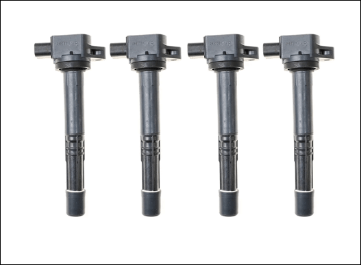
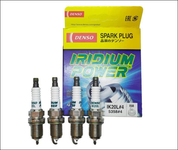
IGNITION SYSTEM
The parts of the ignition system are the four (4) sparkplugs, its corresponding four (4) ignition coils, and the ignition coil relay. Each ignition coils have their own ICMs (Ignition Control Module) that are connected to the ECM/PCM, which controls the timing of the firing of the sparkplugs.

Honda Civic Charging System Parts
Honda Civic Ignition System Parts
Video: How to Replace Ignition Coils 06-11 Honda Civic L4 1.8L
References on Honda Civic Wiring Diagram
Replace a Defective Key Fob for Six Dollars – Replace a defective key fob by installing a new central locking system that includes two (2) brand new key fobs.
https://www.civicforums.com/forums/328-electrical/159859-meet-your-eld-electrical-load-detector.html – Electrical Load Detector (ELD), where it is located, its function, and possible modifications.