The ESP-01 ESP8266 module can be controlled directly, without using any WiFi router at all. To extend the range of the ESP-01 control, it can be connected and controlled thru a wireless router. In this way, the ESP-01 can even be accessed anywhere in world where there is an Internet connection.
ESP-01 Station and Access Point Mode
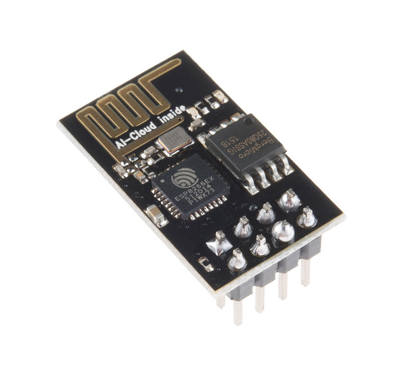
The ESP-01 module or any ESP8266-based microcontroller may be operated in three different modes. It can be used as a station (STA mode), an access point (AP mode), or both (STA + AP mode). In order to control the ESP-01 module thru the router, we will put the ESP-01 in station mode (STA mode).
ESP-01 Programmer-Flasher
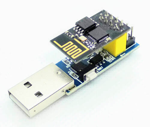
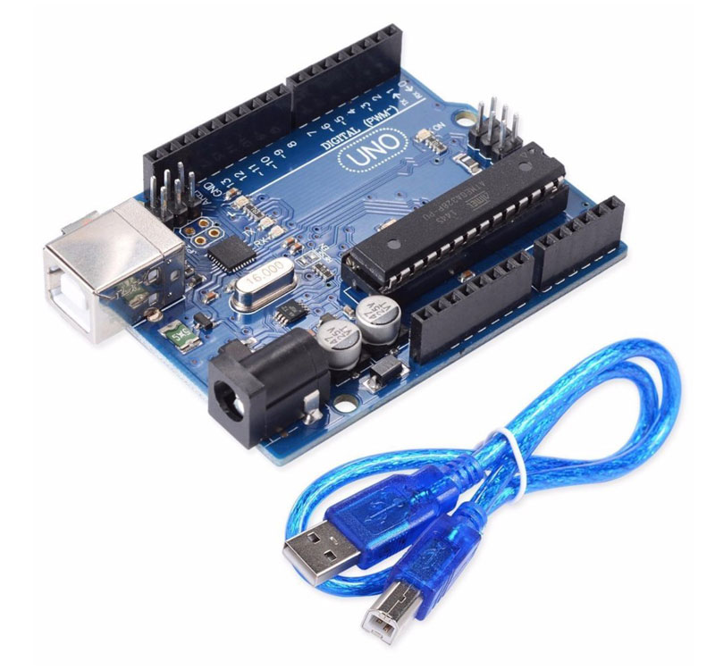
The ESP-01 module, being the smallest and the cheapest of all ESP8266 modules, does not have a built-in programmer or flasher. It can be flashed using a Programmer adapter, an Arduino board or may be wired with a USB to TTL Converter to make a programmer-flasher.
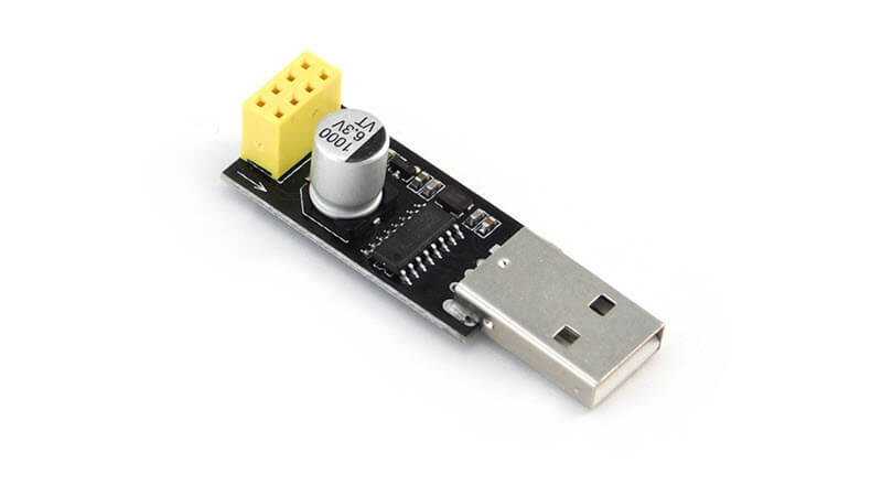
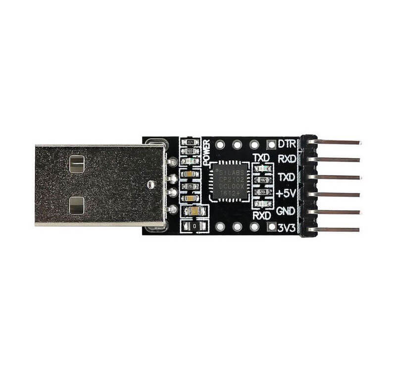
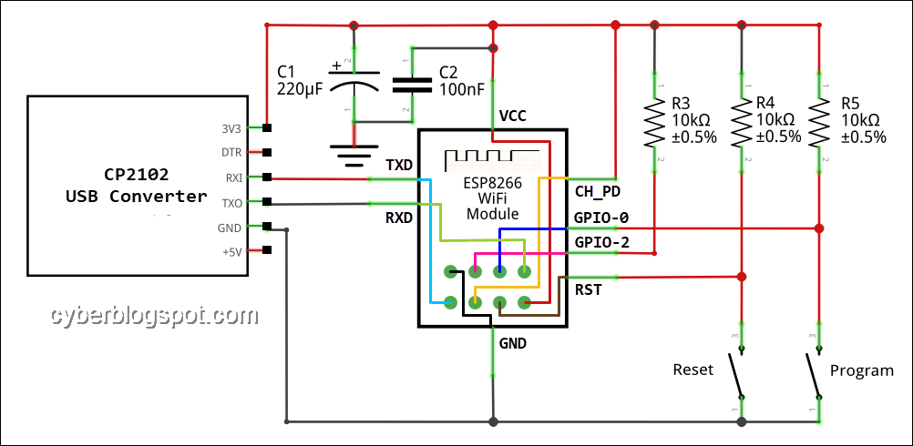
The preferred way of flashing an ESP-01 during testing and breadboarding is to use a USB to TTL converter with a two (2) pushbutton and three (3) 10K ohm resistors. In this way, additional devices can be added later on without changing the circuit. To learn how to use this programmer/flasher, please see: How to Program ESP-01 with Arduino IDE.
For example, using the schematic diagram above, you can add an LED on both the GPIO-0 and GPIO-2 without any changes. Just connect a current limiting resistor in series with the LED and connect it directly to GPIO-0 or GPIO-2 terminal and the ground.
Also later on, when you progress to experimenting with LCD display (Liquid Crystal Display) and Real Time Clock (RTC) modules, both devices and can be connected directly to GPIO-0 and GPIO-2 acting as SDA and SCL terminals for I2C communication. No changes at all on the programmer/flasher circuitry!!!
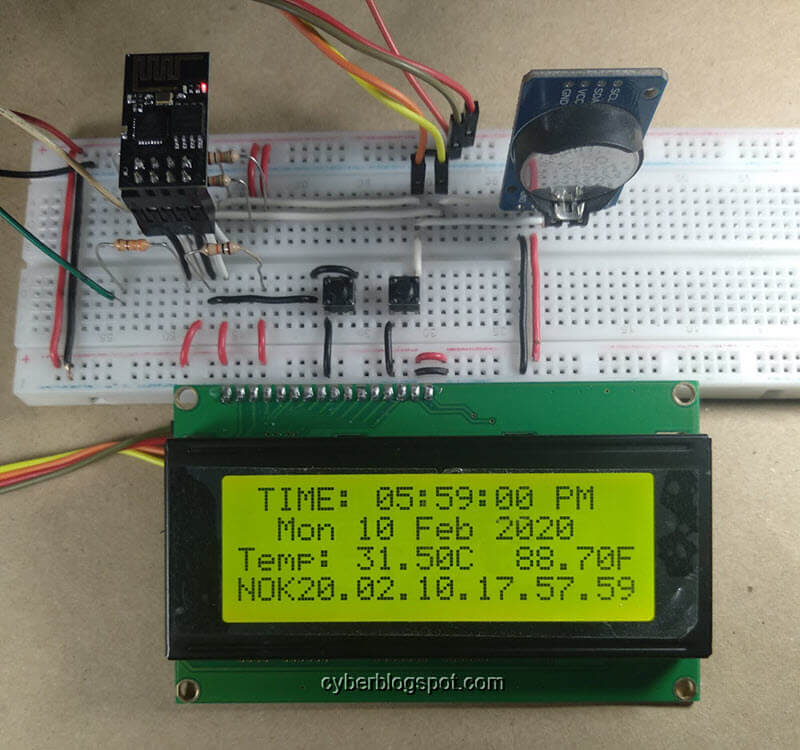
Learn How to Create LCD Clocks with ESP-01 ESP8266 module
ESP-01 with RTC and LCD Display
ESP-01 NTP Clock with LCD Display
Arduino IDE Sketch to Control ESP-01 thru a Router
Version 1 – Does not Use ESP8266Webserver Library
/*
 * esp01-stamode-noweb-library.ino
 *
 * Put ESP-01 ESP8266 Module into Station mode, connect to a
 * router and provide a web server for turning a LED on and off
 *
 * Written by www.cyberblogspot.com, 22February2020
 * Based on Library Examples
 *
 * Sketch Resources
 * Program storage: 273160 bytes (28%)
 * Global variables: 27356 bytes (33%)
 *
 */
#include <ESP8266WiFi.h>
/* Set to SSID and password of router */
const char *ssid = "ssid";
const char *password = "password";
int ledPin = 2; // GPIO2 of ESP8266 available on ESP-01
WiFiServer server(80); // server port 80
void setup() {
  Serial.begin(115200);

  Serial.println();
  Serial.println("Starting ESP-01 Station Mode...");

  WiFi.mode(WIFI_STA);
  WiFi.begin(ssid, password);
  Serial.println("Connecting to WiFi Router");
  while (WiFi.status() != WL_CONNECTED) {
    delay(500);
    Serial.print(".");
  }
  Serial.println();
  Serial.print("IP address: ");
  Serial.println(WiFi.localIP());

  server.begin();
  Serial.println("ESP-01 Web Server ready...");
  Serial.println();
  pinMode(ledPin, OUTPUT);
  digitalWrite(ledPin, LOW);
}
void loop() {

  // Check if a client has connected

  WiFiClient client = server.available();
  if (!client) {
    return;
  }

  // Wait until the client sends some data

  Serial.println("new client");
  while(!client.available()){
    delay(1);
  }
  // Read the first line of GET containing request command

  String request = client.readStringUntil('\r');
  Serial.println(request);
  client.flush();
  // Check command string and perform request
  int value = LOW;

  if (request.indexOf("/gpio/0") != -1){
    digitalWrite(ledPin, LOW);
    value = LOW;
  }

  if (request.indexOf("/gpio/1") != -1) {
    digitalWrite(ledPin, HIGH);
    value = HIGH;
  }

  // Server Response
  // Header
  client.println("HTTP/1.1 200 OK");
  client.println("Content-Type: text/html");
  client.println(""); // header end marker
  // Content
  client.println("<!DOCTYPE HTML>");
  client.println("<html>");
  client.print("LED STATUS: ");
  if(value == HIGH)
    client.print("ON");
  else
    client.print("OFF");
  client.println("<br><br>");
  client.println("<a href=\"/gpio/1\">TURN ON LED</a><br>");
  client.println("<a href=\"/gpio/0\">TURN OFF LED</a><br>");
  client.println("</html>"); // content end
  // End of Response
  delay(1);
  Serial.println("Client disconnected");
  Serial.println("");
}
Version 2 – Using ESP8266Webserver Library
/*
 * esp01-stamode-webserver-library.ino
 *
 * Written by www.cyberblogspot.com
 * 22February2020
 *
 */

#include <ESP8266WiFi.h>
#include <WiFiClient.h>
#include <ESP8266WebServer.h>
//SSID and Password to your ESP Access Point
const char* ssid = "ssid";
const char* password = "password";
int ledPin = 2;
ESP8266WebServer server(80); //Server on port 80
void handleRoot() {
  String s = "<html>\
  LED STATUS: <br><br>\
  <a href=\"/gpio/1\">TURN ON LED</a><br>\
  <a href=\"/gpio/0\">TURN OFF LED</a><br>\
  </html>";

  server.send(200, "text/html", s);
}
void handleGpioOn() {
  String s = "<html>\
  LED STATUS: ON<br><br>\
  <a href=\"/gpio/1\">TURN ON LED</a><br>\
  <a href=\"/gpio/0\">TURN OFF LED</a><br>\
  </html>";

  server.send(200, "text/html", s);
  digitalWrite(2, HIGH);
}
void handleGpioOff() {
  String s = "<html>\
  LED STATUS: OFF<br><br>\
  <a href=\"/gpio/1\">TURN ON LED</a><br>\
  <a href=\"/gpio/0\">TURN OFF LED</a><br>\
  </html>";
  server.send(200, "text/html", s);
  digitalWrite(2, LOW);
}
void setup(void){
  Serial.begin(115200);

  Serial.println("");
  Serial.println("Starting ESP-01 Station Mode...");

  WiFi.mode(WIFI_STA);
  WiFi.begin(ssid, password);
  Serial.println("Connecting to WiFi Router");
  while (WiFi.status() != WL_CONNECTED) {
    delay(500);
    Serial.print(".");
  }

  Serial.println();
  Serial.print("IP Address: ");
  Serial.println(WiFi.localIP());

  server.on("/", handleRoot);
  server.on("/gpio/0", handleGpioOff);
  server.on("/gpio/1", handleGpioOn);
  server.begin();
  Serial.println("ESP-01 Web Server ready...");
  Serial.println();
  pinMode(2, OUTPUT);
  digitalWrite(ledPin, LOW);
}
void loop(void){
  server.handleClient();          //Handle client requests
}
Related Articles on How to Control ESP-01 thru a Router
Hardware
NodeMCU ESP32S Pin Configuration
NodeMCU V3 ESP8266 Pinout and Configuration
How to Save and Restore ESP8266 and ESP32 Firmware
How to Test NodeMCU V3 Using Esptool
How to Connect a DS3231 to NodeMCU V3
Software
How to Install Arduino IDE on Windows 10
How to Set up Arduino IDE for ESP8266 Programming
How to Install Esptool on Windows 10
References on How to Control ESP-01 thru a Router
ESP8266 on Wikipedia
ESP-01 AI–Thinker Website
ESP-01 ESP8266 Module Espressif Website
A Beginner’s Guide to the ESP8266