The ESP-01 module is the smallest and the cheapest of all ESP8266 development boards. People usually program it for use via the Internet. The ESP-01 connects to a router and an application accesses it thru the Internet. But I am interested in how to connect and control the ESP-01 without an internet connection. And most of all, I want to control the ESP-01 without using a router.
ESP-01 ESP8266 Module Operating Modes
Every ESP8266 module has three operating modes:
- Station Mode (STA)
- Soft Access Point (AP) Mode
- Soft AP + Station Mode
In Station Mode (STA), the ESP8266 connects wirelessly to an existing network thru a router. Any device, such as a smartphone, a PC, or a laptop wishing to communicate and control the ESP8266 module must also connect to the router.
In Soft Access Point (AP) mode, the ESP8266 acts like a router. It becomes an Access Point (AP). Other devices can directly connect and communicate with it.
Finally, in the Soft AP + Station mode, the ESP8266 operates on both modes. It connects to other devices and at the same time it can accept connections from other devices.
Controlling the ESP-01 Without a Router
To control the ESP-01 ESP8266 module without a router or an internet connection, the ESP-01 is placed into AP mode (Accesss Point mode). A smartphone or a PC with wireless capability is then used to connect to the module. Command codes are then sent to it thru a browser or an application.
Have you just bought a new ESP-01 Wi-Fi module? Take a look at
How to Test an ESP-01 ESP8266 Module
Learn how to differentiate between ESP-01 and ESP-01S Wi-Fi modules, see:
Difference Between ESP-01 and ESP-01S
For a complete list of ESP-01 programmers, visit:
ESP-01 and ESP-01S Pinout and Configuration
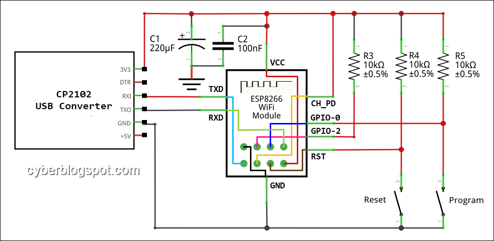
On the hardware side, the ESP-01 needs a programmer or has to be wired with a USB to TTL converter. See the schematic diagram below:
How to Use the Program
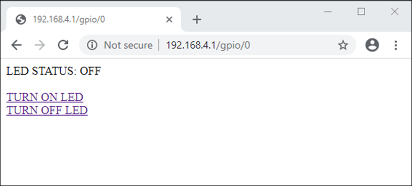
The following program will control the ESP-01 module by turning on and off the blue built-in LED on the ESP-01 module. Upload the sketch to the ESP-01 module. Then, connect to the ESP-01 access point using a smartphone or a PC with a wireless network adapter. The SSID of the ESP-01 module is “ESP01” and the password is “password”. After successfully connecting to the access point, open an internet browser. On the address bar, type “192.168.4.1/gpio/1” to turn on the blue LED light. Turn the LED off, type “192.168.4.1/gpio/0”.
Code Without ESP8266Webserver Library
Code Explanation
This Arduino IDE sketch uses the ESP8266WiFi library.
#include <ESP8266WiFi.h>
A server object is created during initialization specifying the port to use.
WiFiServer server(80);
The ESP8266 is placed into AP mode inside the setup() function with the SSID and password to use in connecting to the ESP8266 wifi access point.
WiFi.softAP(ssid, password);
Also in the setup() function, the web server is started.
server.begin();
In the main loop() function, the web server is checked for any connecting client.
WiFiClient client = server.available();
if (!client) {
  return;
}
To fully understand the next lines of code, let us review some HTTP basics.
When we type an IP address on a browser’s URL or address bar and press the return key, the browser sends a GET request to the web server with the typed IP address. For example, if we type the IP address “192.168.4.1”, it gets translated by the browser into “GET /“. Any string that we append to the URL gets appended to the GET request. If we type “192.168.4.1/gpio”, the GET request becomes “GET /gpio“.
The next line of code reads the connected client’s GET request and store it in a String object request.
String request = client.readStringUntil('\r');
Serial.println(request);
client.flush();
Next the request string is checked for the presence of the LED command strings: “gpio/0” to turn off the LED and “gpio/1” to turn on the LED. It performs the requested operation if one of the command strings is found.
if (request.indexOf("/gpio/0") != -1){
  digitalWrite(ledPin, LOW);
  value = LOW;
}

if (request.indexOf("/gpio/1") != -1) {
  digitalWrite(ledPin, HIGH);
  value = HIGH;
}
Finally, a response string is sent to the requesting client.
// Server Response
  // Header
  client.println("HTTP/1.1 200 OK");
  client.println("Content-Type: text/html");
  client.println(""); // header end marker
  // Content
  client.println("<!DOCTYPE HTML>");
  client.println("<html>");
  client.print("LED STATUS: ");
  if(value == HIGH)
    client.print("ON");
  else
    client.print("OFF");
  client.println("<br><br>");
  client.println("<a href=\"/gpio/1\">TURN ON LED</a><br>");
  client.println("<a href=\"/gpio/0\">TURN OFF LED</a><br>");
  client.println("</html>"); // content end
  // End of Response
The response string is displayed on the browser. See the screenshot below.
The output of the Serial Monitor for debugging purposes.

The Complete Source Code
/*
 * esp01-apmode-noweb-library.ino
 *
 * Put ESP-01 ESP8266 Module into AP mode and
 * provide a web server for turning an LED on and off
 *
 * Written by www.cyberblogspot.com, 20February2020
 * Based on Library Examples
 *
 * Sketch Resources
 * Program storage: 274048 bytes (28%)
 * Global variables: 27308 bytes (33%)
 *
 */
#include <ESP8266WiFi.h>
/* Set to preferred SSID and password */
const char *ssid = "ESP01";
const char *password = "password";
int ledPin = 2; // GPIO2 of ESP8266 available on ESP-01
WiFiServer server(80); // server port 80
void setup() {
  Serial.begin(115200);

  Serial.println();
  Serial.println("Starting ESP-01 Access Point...");

  WiFi.softAP(ssid, password);
  IPAddress espIP = WiFi.softAPIP();
  Serial.print("IP address: ");
  Serial.println(espIP);

  server.begin();
  Serial.println("ESP-01 Web Server ready...");
  Serial.println();
  pinMode(ledPin, OUTPUT);
  digitalWrite(ledPin, LOW);
}
void loop() {

  // Check if a client has connected

  WiFiClient client = server.available();
  if (!client) {
    return;
  }
  /*****************************************************
  NOTE: This snippet from library examples does not work

  // Wait until the client sends some data

  Serial.println("new client");
  while(!client.available()){
    delay(1);
  }
  *****************************************************/
  // Read the first line of GET containing request command

  String request = client.readStringUntil('\r');
  Serial.println(request);
  client.flush();
  // Check command string and perform request
  int value = LOW;

  if (request.indexOf("/gpio/0") != -1){
    digitalWrite(ledPin, LOW);
    value = LOW;
  }

  if (request.indexOf("/gpio/1") != -1) {
    digitalWrite(ledPin, HIGH);
    value = HIGH;
  }

  // Server Response
  // Header
  client.println("HTTP/1.1 200 OK");
  client.println("Content-Type: text/html");
  client.println(""); // header end marker
  // Content
  client.println("<!DOCTYPE HTML>");
  client.println("<html>");
  client.print("LED STATUS: ");
  if(value == HIGH)
    client.print("ON");
  else
    client.print("OFF");
  client.println("<br><br>");
  client.println("<a href=\"/gpio/1\">TURN ON LED</a><br>");
  client.println("<a href=\"/gpio/0\">TURN OFF LED</a><br>");
  client.println("</html>"); // content end
  // End of Response
  delay(1);
  Serial.println("Client disconnected");
  Serial.println("");
}
Code Using ESP8266Webserver Library
Code Explanation
To facilitate programming the ESP-01 module we may also use the ESP8266Webserver library. The following version is another implementation of the same Arduino IDE sketch shown above.
First of all, we include the three (3) libraries that are needed.
#include <ESP8266WiFi.h>
#include <WiFiClient.h>
#include <ESP8266WebServer.h>
/*
 * esp01-apmode-webserver-library.ino
 *
 * Put ESP-01 ESP8266 Module into AP mode and
 * provide a web server for turning an LED on and off
 *
 * Written by www.cyberblogspot.com, 20February2020
 * Based on Library Examples
 *
 */

#include <ESP8266WiFi.h>
#include <WiFiClient.h>
#include <ESP8266WebServer.h>
/* Set to preferred SSID and password */
const char* ssid = "ESP01";
const char* password = "password";
int ledPin = 2; // GPIO2 of ESP8266 available on ESP-01
ESP8266WebServer server(80); // server port 80
void handleRoot() {
  String response = "<html>\
  LED STATUS: <br><br>\
  <a href=\"/gpio/1\">TURN ON LED</a><br>\
  <a href=\"/gpio/0\">TURN OFF LED</a><br>\
  </html>";

  server.send(200, "text/html", response);
}
void handleGpioOn() {
  String response = "<html>\
  LED STATUS: ON<br><br>\
  <a href=\"/gpio/1\">TURN ON LED</a><br>\
  <a href=\"/gpio/0\">TURN OFF LED</a><br>\
  </html>";

  server.send(200, "text/html", response);
  digitalWrite(2, HIGH);
}
void handleGpioOff() {
  String response = "<html>\
  LED STATUS: OFF<br><br>\
  <a href=\"/gpio/1\">TURN ON LED</a><br>\
  <a href=\"/gpio/0\">TURN OFF LED</a><br>\
  </html>";
  server.send(200, "text/html", response);
  digitalWrite(2, LOW);
}
void setup(void){
  Serial.begin(115200);

  Serial.println("");
  Serial.println("Starting ESP-01 Access Point...");

  WiFi.softAP(ssid, password);
  IPAddress espIP = WiFi.softAPIP(); //Get IP address
  Serial.print("IP Address: ");
  Serial.println(espIP);

  server.on("/", handleRoot);
  server.on("/gpio/0", handleGpioOff);
  server.on("/gpio/1", handleGpioOn);
  server.begin();
  Serial.println("ESP-01 Web Server ready...");
  Serial.println();
  pinMode(ledPin, OUTPUT);
  digitalWrite(ledPin, LOW);
}
void loop(void){
  server.handleClient();          //Handle client requests
}
Creating Smartphone App for Controlling ESP-01 Without a Router
Although the ESP-01 module can be controlled by any smartphone using any internet browser application, creating a smartphone app is in order.
There is an online app creator called MIT App Inventor. This is a GUI and drag and drop programming application. Visit the website and create an account.
The following instruction is a step by step guide on how to make a simple application to control the ESP-01 module after being flashed with the software discussed above.
Short MIT App Inventor Tutorial
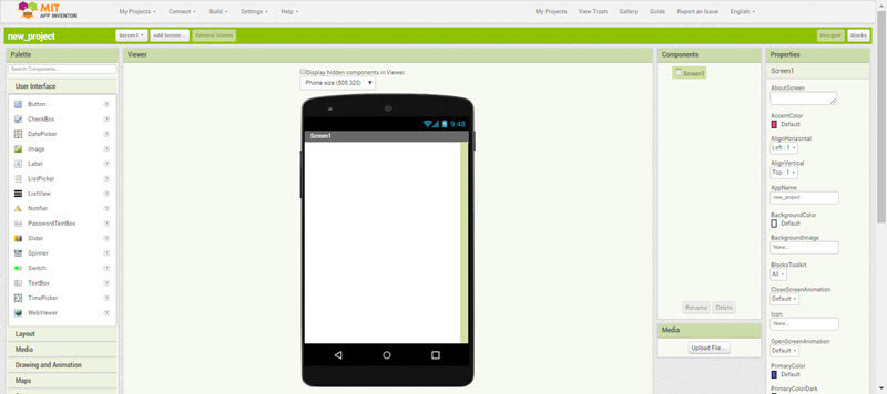
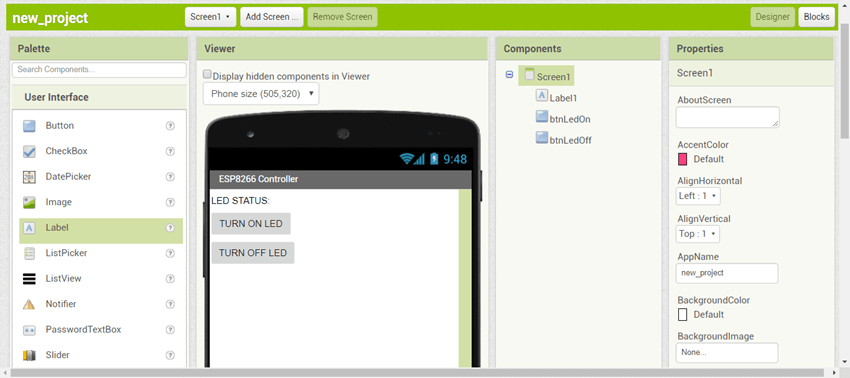
When you open MIT App Inventor and start a new project, the Inventor will show you a window similar to the screenshot above. This is the Designer window. When you are creating an application, you will be switching between the Designer window and the Blocks window shown below.
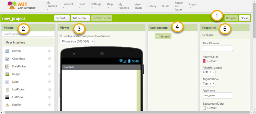
The switching between the Designer window and the Blocks windows is done by clicking the appropriate buttons located near the top right portion of the window, annotated as #1.
The important parts of the Designer window are the Palette pane (#2), Viewer pane (#3), Components pane (#4), and the Properties pane (#5).
The Palette pane is where you get the different components like Buttons and Labels. You drag the components and drop them onto Viewer pane. All the dropped components will show on the Components pane. The properties of the different components are changed in the rightmost pane or the Properties pane.
The Blocks window may need no introduction as it only contains a Blocks pane and the Viewer pane. The Blocks pane contains the programming blocks that are dragged from it and dropped into the Viewer pane.
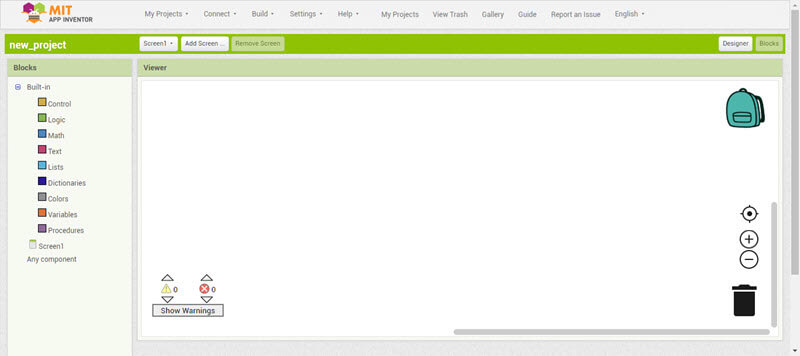
Creating the App
Create a new project and drag and drop a Label and two (2) Buttons from the Palette into the screen of the smartphone image. Next, find Connectivity under the Palette pane and also drag and drop a Web component.
Notice that the Web component does not show on the screen of the smartphone because it is a non-visible component. Instead, the Web component is shown outside, underneath the phone.
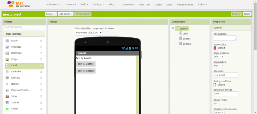
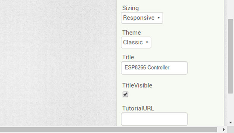
Change the title of the screen. Click Screen1 on the Components pane to select it and then scroll down on the Properties pane. Search for Title and type ESP8266 Controller.
In the same manner change the Text property of Label1. Click Label1 on the Components pane and look for the Text property. Then type in LED STATUS:.
In the next step, rename Button1 to btnLedOn and change its Text property to TURN ON LED. Do the same with Button2. Rename Button2 to btnLedOff and then change its Text property to TURN OFF LED.
To rename a component, select the component from Components pane and click the RENAME button located near the bottom of the pane.
We renamed Button1 and Button2 to btnLedOn and btnLedOff respectively, in order to make it easy to remember which is which and to distinguish the buttons (btn) from the other components when we switch to programming using Blocks.
Now, we are ready for programming. Switch into the Blocks window by clicking on the Blocks button near the top right section of the screen.
Below is a screenshot of the completed Blocks for the ESP8266 Controller app. We will use this as a guide in building the Blocks sections.
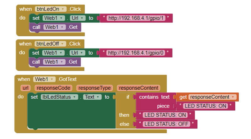
- On the Blocks pane, click the btnLedOn button and drag a when btnLedOn.Click block into the Viewer.
- Click on the component Web1, locate a set Web1.Url to block, and drag the block inside the btnLedOn.Click block.
- Click on a Text component on the Blocks pane under Built-in. Drag an empty Text String block and connect it to the end of the set Web1.Url to block. Then, type http://192.168.4.1/gpio/1 inside the Text String block.
- Click again on the Web1 component on the Blocks pane and get a call Web1.Get block. Drag the block inside the when btnLedOn.Click block below the set Web1.Url to block.
Now that we’re done with the first Block section, let’s take a look at what we have done. The program block is interpreted as follows: when the btnLedOn button is clicked, the Web1 component is set to the command for turning on the LED (http://192.168.4.1/gpio/1). The Web1 component will then issue an HTTP GET method.
For the second button, btnLedOff, we can simply duplicate the first block. Right click on the completed block and select Duplicate on the context menu. Make the necessary changes by changing btnLedOn to btnLedOff and replacing http://192.168.4.1/gpio/1 to http://192.168.4.1/gpio/0.
Now for the final block of the app to control the ESP-01 without the use of a router:
- Click Web1 on the Blocks pane and drag a when Web1.GotText block.
- Click on Label1 and drag a set Label1.Text to block and drop it inside the when Web1.GotText block.
- Then select Control from Built-in and drag an if-then-else block and connect it to end of the set Label1.Text to block.
- Click Text from Built-in and drag a contains Text block, connecting it on the if slot of the if-then-else block.
- Again, select Text from Built-in and drag two empty Text String blocks, placing them on the then and else slots of the if-then-else block. Type LED STATUS: ON and LED STATUS: OFF on the respective Text String blocks.
- Put the mouse over the responseContent of when Web1.GotText block. Drag a get responseContent block and attach it to contains Text block slot. Finally, get another Text String and attach it to the piece slot of the contains Text block. Complete the block by typing LED STATUS: ON on the empty Text String.
Now you can build and test the completed ESP8266 Controller android smartphone app.
Related Articles on How to Control ESP-01 Without a Router
Hardware
How to Program ESP-01 with Arduino IDE
ESP-01 with RTC and LCD Display
ESP-01 NTP Clock with LCD Display
NodeMCU ESP32S Pin Configuration
NodeMCU V3 ESP8266 Pinout and Configuration
How to Save and Restore ESP8266 and ESP32 Firmware
How to Test NodeMCU V3 Using Esptool
How to Connect a DS3231 to NodeMCU V3
How To Compute Resistor Value for LED
Software
How to Install Arduino IDE on Windows 10
How to Set up Arduino IDE for ESP8266 Programming
How to Install Esptool on Windows 10
References on How to Control ESP-01 Without a Router
ESP8266 on Wikipedia
MIT App Inventor
Hello, great article – thank you! I ran the code and it worked perfectly! Will the ESP8266 always get the IP address of 192.168.4.1? Is there any way to assign it’s IP?
ok, thank you very much
Thanks to helpfull nots