The Serial Monitor in Arduino IDE is an indispensable tool for debugging purposes. However, although a Digispark ATtiny85 development board has a USB interface, the Serial Monitor does not work with it. The main reason is that the USB interface in the Digispark board is not a serial COM port. The second reason is that the ATtiny85 chip does not have a UART port. And third, the Digispark board lacks a UART to USB bridge circuitry to translate UART signals to USB signals. In this article, we will take a look at how to enable the Serial Monitor when using a Digispark ATtiny85 development board.
To enable the Arduino IDE Serial Monitor on a Digispark ATtiny85 board, connect a USB-to-Serial converter. Then use the SoftwareSerial library in the Arduino IDE to create a UART port on the ATtiny85 chip.
For Digispark ATtiny85 pinout guide, kindly see Digispark ATtiny85 Pinout and Configuration.
Step by Step Guide For Serial Monitor
STEP 1 – Connect a USB-to-Serial Converter
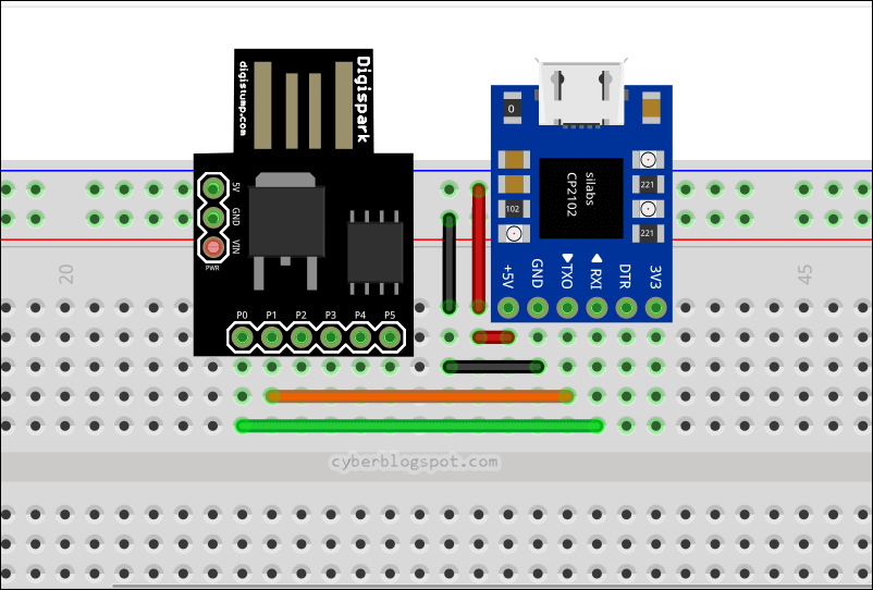
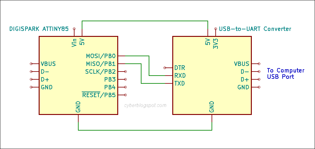
First, connect a USB-to-serial converter to the Digispark ATtiny85 board as shown in Figure 1 and Figure 2.
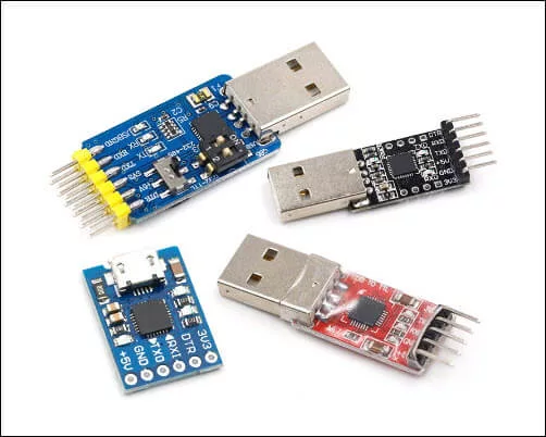
There are many inexpensive USB-to-serial converters on the Internet. Examples of USB-to-serial converters are shown below in Figure 3. These converters are sometimes referred to as USB-to-serial TTL converters or USB-to-UART converters. Also, the converters use a variety of chips, hence, they may be referred to by their chip names. Some of the popular USB-to-serial chip names that you may encounter are FTDI, CP2104, CH304, and PL2303.
STEP 2 – Install the USB-to-Serial Converter Device Driver
Download and install the device driver for your USB-to-serial converter. Because USB-to-serial converters use different chips, you need to search the internet for the device driver for your particular USB-to-serial converter.
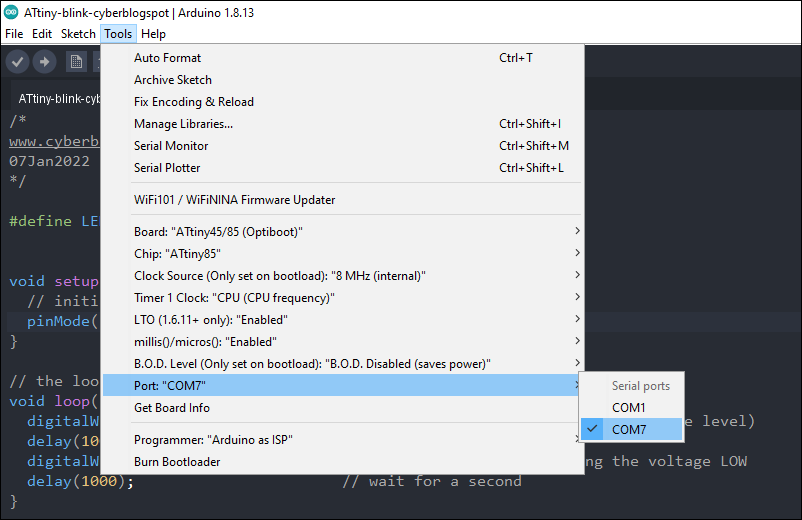
You can do a quick test if you have the right device driver installed. Open the Arduino IDE and go to the Tools/Port menu. You should see an additional port instead on only COM1 on the Serial Ports list when you plug in your USB-to-serial converter. Please see Figure 4.
STEP 3 – Install the Board Core ATTinycore by Spence Konde
Although we may use the original Digistump AVR board core, I prefer to use the ATTinyCore as it supports almost all of the ATtiny line of AVR chips. Additionally, the ATTinyCore gives us the option to program the ATtiny85 in several ways: no bootloader, Optiboot, and Micronucleus (Digispark) modes. If you need help in installing the ATTinyCore, please see How to Install ATTinyCore on Arduino IDE.
STEP 4 – Use Software Serial to Create UART Ports on ATtiny85
Open the Arduino IDE and upload the sketch shown below. If you need help in uploading the sketch using the board core ATtinyCore, you may visit How to Program Digispark ATtiny85 Board with Arduino IDE.
IMPORTANT NOTE
Before hitting the Upload button to install the sketch, unplug both USB cables for the Digispark board and the USB-to-serial converter. Plug in the USB cable for the Digispark board when prompted by the Arduino IDE. When the sketch upload is done, unplug the USB cable from the Digispark board. Connect the USB cable for the USB-to-serial converter and proceed to STEP 5 for testing the Serial Monitor.
/* cyberblogspot.com 15Jan2023 */

#include "SoftwareSerial.h"

SoftwareSerial mySerial(1, 0);  //RX, TX  PB1, PB0

void setup() {
  mySerial.begin(19200);

  mySerial.println("Change baud rate to 19200");
  mySerial.println("Type something and press ENTER");
}

void loop() {
  if (mySerial.available()){
    mySerial.println(mySerial.readString());
  }
}
The sketch above needs no explanation. Simply include the library header file for the SoftwareSerial library. You do not have to download the SofwareSerial library as it should come with the ATtinyCore board core installation.
Regarding the code creating the SoftwareSerial object in line 5,
SoftwareSerial mySerial(1, 0); //RX, TX PB1, PB0
you may use any two (2) available ATtiny85 ports available. In this case, I used PB1 for RX (receiver) and PB0 for TX (transmitter).
STEP 5 – Test the Serial Monitor
After uploading the sketch to the Digispark ATtiny85 board, unplug the USB cable from the Digispark board. Plug in the USB cable for the USB-to-serial converter.
Then, select the correct COM port for your USB-to-serial converter in the Arduino IDE “Tools/Port” menu. Test the program and you should now be able to use the Serial Monitor on the Digispark ATtiny85 board.
References on How to Enable Serial Monitor on Digispark ATtiny85
USB-to-serial adapter – Wikipedia article on USB to Serial Converter
How to Install Arduino IDE on Windows 10
How to Install ATTinyCore on Arduino IDE
How to Use Arduino as ISP Programmer
How to Program ATtiny85 with Arduino IDE
Digispark ATtiny85 Pinout and Configuration
How to Program Digispark ATtiny85 Board with Arduino IDE
Digispark USB Device Not Recognized
How to Use AT-09 BLE with Arduino and Smartphone
Very good step by step explanation. Is there a possibility to get the schematic and layout as fritzing project?
hello,
Thank you for everything. When I choose Digistump AVR Board, this will not compile and then will not upload the code in attiny85 !! do you have any solution ? Thank you