There are three (3) ways to program an ATtiny85 chip with Arduino IDE. That is, we can upload sketches from the Arduino IDE to ATtiny85 in several ways. These include the use an AVR programmer, a Micronucleus bootloader, or an Optiboot bootloader.
In order to use all these programming modes, we need to install the ATTinyCore. It is an Arduino core designed for the ATtiny family of MCUs. Please see How to Install ATTinyCore on Arduino IDE.
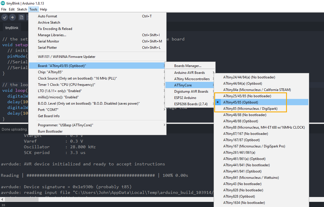
If we install the ATTinyCore in the Arduino IDE, we would get the ATTinyCore board menu shown below. Based on the menu, to program an ATtiny85 in Arduino IDE, three (3) options exists. These are the No bootloader, Optiboot, and Micronucleus/DigiSpark.
Program ATtiny85 in Arduino IDE Using an AVR Programmer (No Bootloader)
What is a Bootloader
Actually, the Arduino IDE recognizes an MCU board because of a bootloader. A bootloader is a small software that resides in the flash memory of a microcontroller. Its main function is to detect an incoming program upload. If it sees one, it takes the program and stores it in the flash memory. Otherwise, it runs a previously loaded program, if any exist.
Without a bootloader, the Arduino IDE cannot directly program or upload sketches to an ATtiny85 chip. Or for that matter, any microcontroller at all.
AVR Programmers
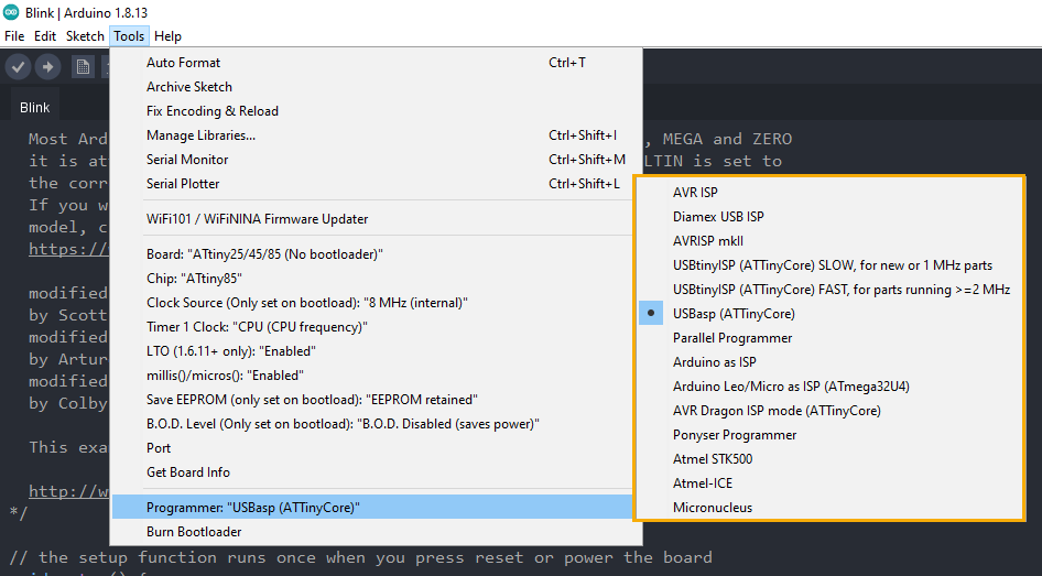
Now, in the absence of a bootloader, how do we program or upload sketches to ATtiny85 using the Arduino IDE? We need an AVR programmer. There are many kinds of AVR programmers. We can see the list of AVR programmers supported by ATtinyCore in the Tools -> Programmer menu.
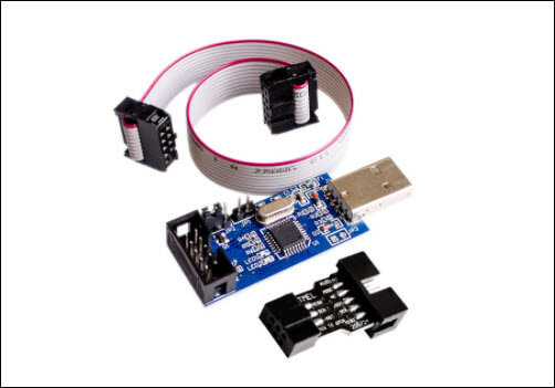
Shown below is a picture of a USBasp ICSP AVR programmer. USBasp is an open-source AVR programmer that you can build by yourself. Or you can buy it cheap on the Internet. It sells for around two dollars ($2) only.
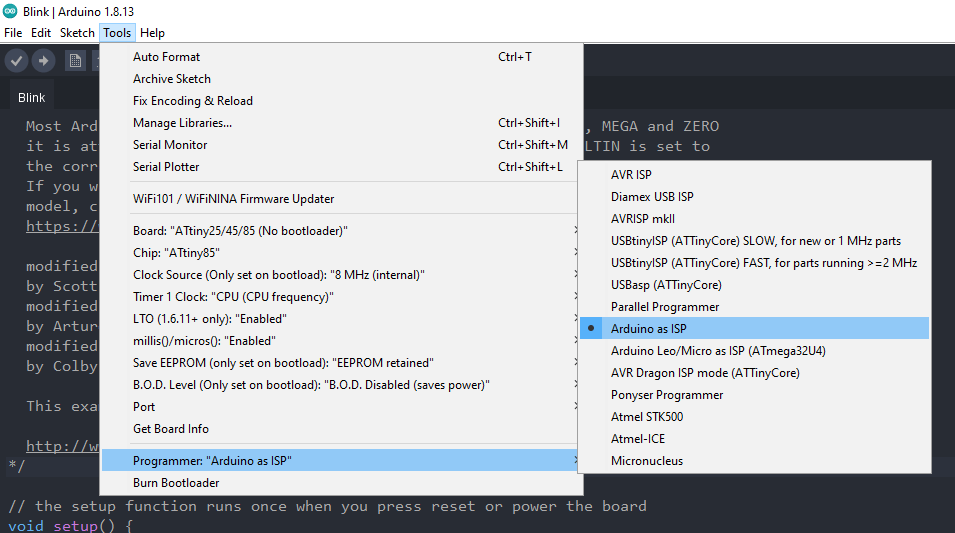
If you don’t have an AVR programmer but you have an Arduino board lying around, you’re good to go. You can use an Arduino board as an AVR programmer. It is one of the options in the ATtinyCore list of programmers – Arduino as ISP. See How to Program ATtiny85 with Arduino.
Wiring the ATtiny85 to an AVR Programmer
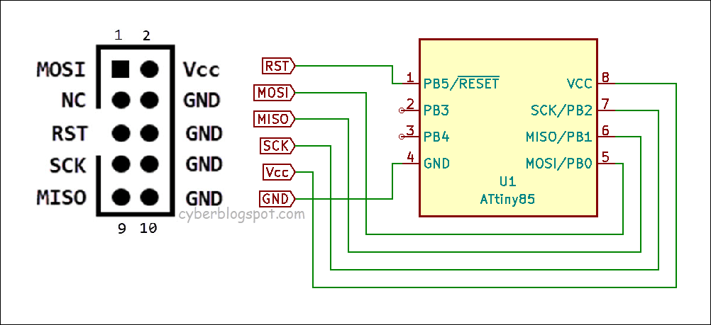
Connecting the ATtiny85 to an AVR programmer is straightforward. We connect the six (6) pins of the AVR programmer to the corresponding six (6) pins of the ATtiny85 chip. That is, we connect the following pins:
PROGRAMMER ATTINY85
MOSI (Pin 1) –> MOSI (Pin 5)
MISO (Pin 9) –> MISO (Pin 6)
SCK (Pin 7) –> SCK (Pin 7)
RST (Pin 5) –> RESET (Pin 1)
VCC (Pin 2) –> VCC (Pin 8)
GND (Pin10) –> GND (Pin4)
Uploading Sketch using AVR Programmer
- Connect the ATtiny85 chip to the AVR programmer as shown in the diagram above.
- Connect the AVR programmer to the USB port of a computer running the Arduino IDE. You may have to install a device driver for your AVR programmer. If you are using a USBasp programmer like the one shown above, you need to download and run Zadig. This will install the device driver needed by the USBasp programmer.
- Open the Arduino IDE. On the main menu, open Tools –> Board –> ATtinyCore and select the board ATtiny25/45/85(No bootloader).
- Next, open Tools –> Programmer and select your AVR programmer. In my case, I would select USBasp(ATTinyCore).
- Create your sketch or open an existing sketch you want to upload to the ATtiny85 chip. To start uploading, press the Upload button (right arrow icon). Or you may open Sketch on the main menu and select either Upload or Upload Using Programmer.
Burning Bootloaders
Besides uploading sketches, we use the AVR programmer to burn bootloaders. That is, we can upload bootloaders like Optiboot and Micronucleus into an ATtiny85 chip.
How to Burn ATtiny85 Chip with Optiboot Bootloader
- On the main menu, open Tools –> Board –> ATtinyCore and select the board ATtiny45/85(Optiboot).
- Next, open Tools –> Programmer and select your AVR programmer.
- Finally, open Tools and click on the Burn Bootloader.
How to Burn ATtiny85 Chip with Micronucleus Bootloader
- On the main menu, open Tools –> Board –> ATtinyCore and select the board ATtiny85(Micronucleus/Digispark).
- Next, open Tools –> Programmer and select your AVR programmer.
- Finally, open Tools and click on the Burn Bootloader.
Program ATtiny85 in Arduino IDE using Optiboot Bootloader
If you have been programming an Arduino board (Uno, Nano, etc.) using the Arduino IDE, then you have been using the Optiboot bootloader. The Arduino IDE uploads sketches to an Arduino board by communicating with the Optiboot bootloader. The communication is done thru a serial port. That is why before you upload a sketch, you need to select the proper serial port (COM port).
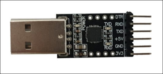
The ATtiny85 chip does not have a serial device. Therefore, to connect it to the PC running the Arduino IDE, we must provide a USB to serial converter. Shown below is an example of a USB serial converter.
Connecting USB Serial Converter to ATtiny85
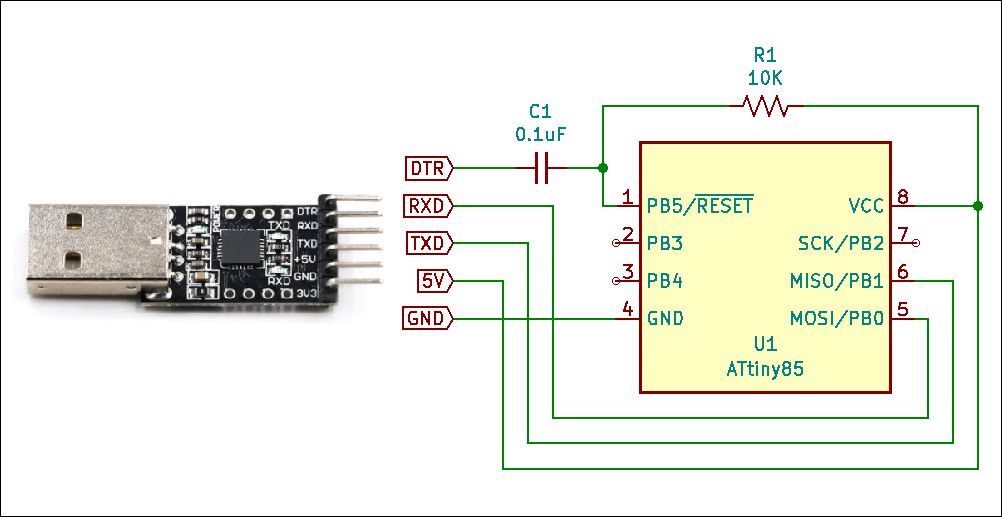
We need to connect the following terminals:
Serial Converter ATtiny85
DTR –> RESET (Pin 1)
RXD –> MOSI (Pin 5)
TXD –> MISO (Pin 6)
5V –> Vcc (Pin 8)
GND –> GND (Pin 4)
Note that the DTR terminal from the serial converter does not connect directly to the RESET pin of the ATtiny85. It is connected via a 0.1uF ceramic capacitor. Moreover, a 10K-ohm pull-up resistor is connected to the RESET pin of the ATtiny85.
Uploading Sketch Using Optiboot Bootloader
- Burn or flash the ATtiny85 with Optiboot bootloader. See above topic – How to Burn ATtiny85 Chip with Optiboot Bootloader.
- Connect the ATtiny85 chip to a USB serial converter as shown in the diagram above.
- Connect the USB serial converter to a computer running the Arduino IDE. You may have to install a device driver for your USB serial converter.
- Open the Arduino IDE. On the main menu, open Tools –> Board –> ATtinyCore and select the board ATtiny45/85(Optiboot).
- Next, open Tools –> Port and select the serial port (COM port) of the serial converter.
- Create your sketch or open an existing sketch you want to upload to the ATtiny85 chip. To start uploading, press the Upload button (right arrow icon). Or you may open Sketch on the main menu and select Upload.
Program ATtiny85 in Arduino IDE using Micronucleus/Digispark
Micronucleus is a bootloader like the Optiboot bootloader discussed above. However, Micronucleus does not use a serial port (COM port) to communicate with the Arduino IDE. Instead, it uses a virtual USB device. This virtual device is installed on the computer hosting the Arduino IDE. The virtual USB serves as a go-between for Micronucleus and the Arduino IDE.
On the hardware side, an ATtiny85 with a Micronucleus bootloader needs a USB connector. The USB connector allows it connect to the USB port of the computer running the Arduino IDE.
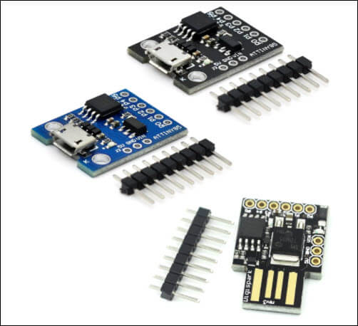
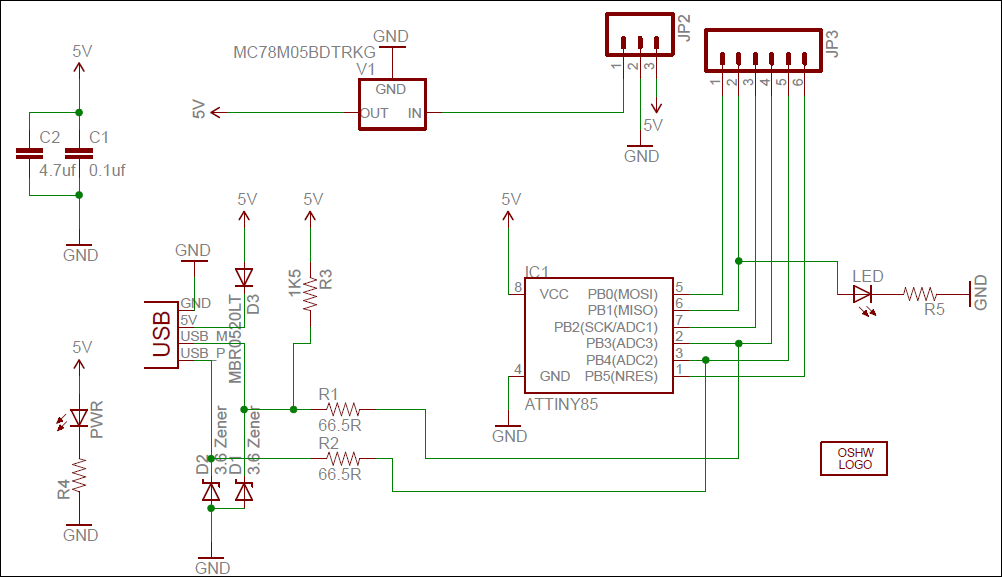
Digispark Development Board
Now comes the Digispark board. It is a small board fitted with an ATtiny85 chip pre-programmed with the Micronucleus bootloader. Also, the board has the required USB connector. And as a bonus, the board includes a 5V voltage regulator, a power indicator LED, and an extra built-in LED on PB2.
For more information on Digispark ATtiny85, please see:
Digispark ATtiny85 Pinout and Configuration
How to Program Digispark ATtiny85 Board with Arduino IDE
Digispark USB Device Not Recognized
Uploading Sketch Using Digispark Boards
- We need to install the Digispark device driver before the Arduino IDE can recognize it. We can download the Digispark device driver and run the installer. However, we can also use the Zadig software to install the Digispark driver.
- Open the Arduino IDE. On the main menu, open Tools –> Board –> ATtinyCore and select the board ATtiny85(Micronucleus / DigiSpark). There is no need to select the Port because Digispark does not use the serial COM port.
- Create a sketch or open an existing sketch to be uploaded
- Press the Upload button.
- Wait for a message to plug in the Digispark board. After inserting the board’s USB, the uploading of the sketch will continue.
References on How to Program ATtiny85 with Arduino IDE
How to Install Arduino IDE on Windows 10
How to Install ATTinyCore on Arduino IDE
Digispark USB Device Not Recognized
Digispark ATtiny85 Pinout and Configuration
How to Program Digispark ATtiny85 Board with Arduino IDE
Types of AVR Programmers – by Nick Gammon
USBasp Project – USB Programmer for Atmel AVR Microcontrollers