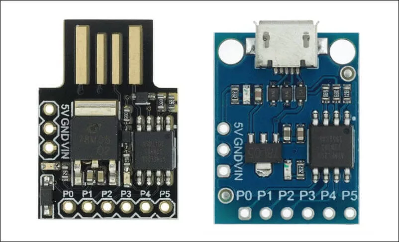
A bare chip ATtiny85 needs to be connected to an ICSP (aka ISP) programmer in order to upload Arduino sketches. To facilitate programming, Digistump created the Digispark ATtiny85 USB Development Board. The Digispark ATtiny85 board does not need an ICSP programmer. Instead, it is directly connected to the USB port of the computer hosting the Arduino IDE. This is the normal way of how to program a Digispark ATtiny85 board.
Difference in Uploading the Sketch
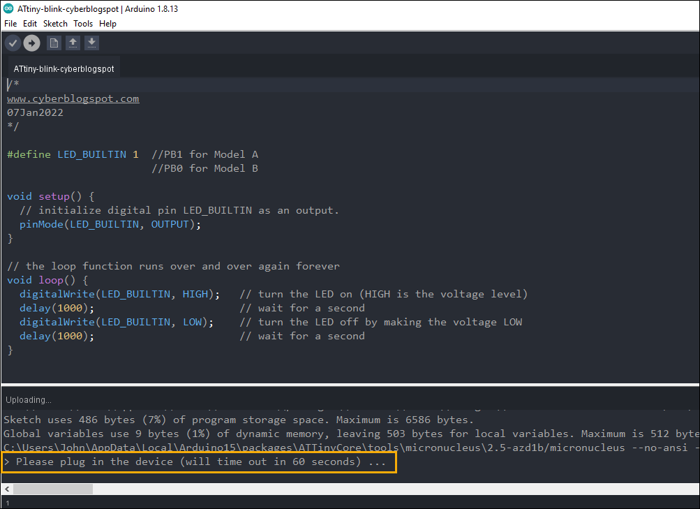
Although a Digispark ATtiny85 board plugs directly into a USB port like any other Arduino development board, there is a slight difference in uploading a program or a sketch. While an Arduino board is connected first to the USB port prior to uploading a sketch, the Digispark board is connected to the USB port after initiating the upload sketch procedure. That is, to upload a sketch to the Digispark board, you have to first press the “Upload” button on the Arduino IDE. Afterwards, a message saying “Please plug in the device (will time out in 60 secs)” will appear on the Arduino IDE. Then, you plug in the Digispark board and the sketch starts uploading. Finally, when the sketch is successfully uploaded, Digispark will run the sketch automatically after five (5) seconds (not instantly as in other Arduino boards).
Configuring Arduino IDE for Digispark ATtiny85 Programming
To program the Digispark ATtiny85 board, first, install the latest version of Arduino IDE if you do not have the Arduino IDE yet on your computer. If you need help on installing the Arduino IDE, please see How to Install Arduino IDE on Windows 10 if you are using Microsoft Windows.
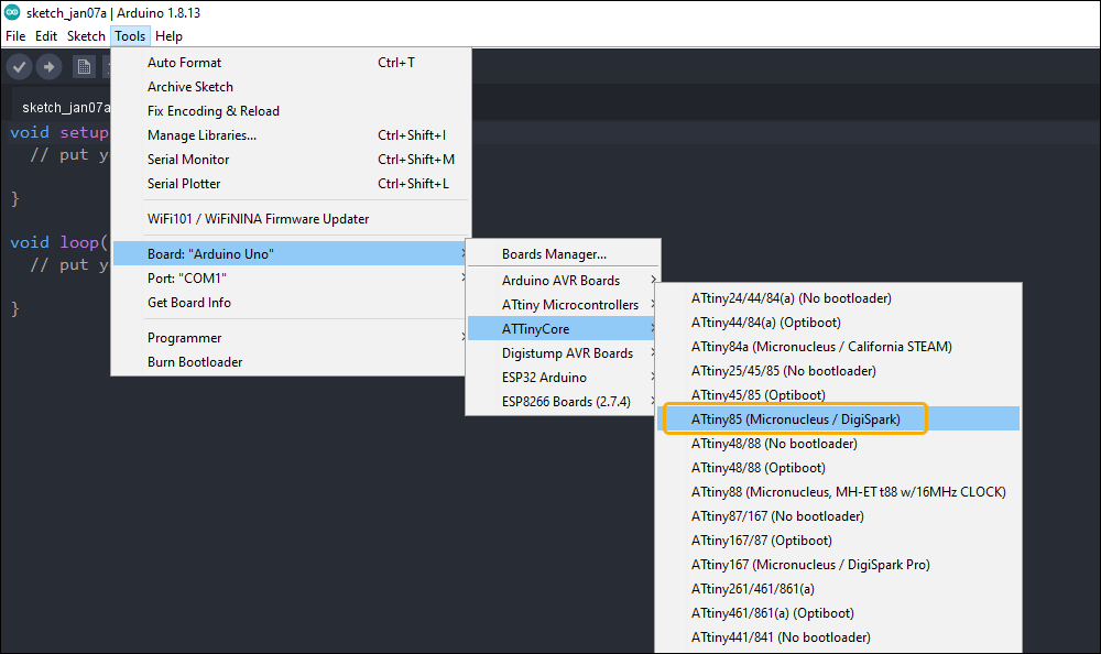
Next, you need to install the ATtinyCore on the Arduino IDE in order for Arduino IDE to recognize the Digispark ATtiny85 boards. You may want to read the article How to Install ATtinyCore on Arduino IDE.
Uploading the Blink Program on Arduino IDE
STEP 1 – Open the Arduino IDE and select the proper board.
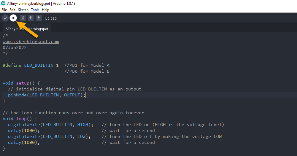
STEP 2 – Create a new sketch. Then copy and paste the sketch below.
/*
www.cyberblogspot.com
07Jan2022
*/

#define LED_BUILTIN 1  //PB1 for Model A
                       //PB0 for Model B

void setup() {
  // initialize digital pin LED_BUILTIN as an output.
  pinMode(LED_BUILTIN, OUTPUT);
}

// the loop function runs over and over again forever
void loop() {
  digitalWrite(LED_BUILTIN, HIGH);   // turn the LED on (HIGH is the voltage level)
  delay(1000);                       // wait for a second
  digitalWrite(LED_BUILTIN, LOW);    // turn the LED off by making the voltage LOW
  delay(1000);                       // wait for a second
}
STEP 3 – Click on the Upload button.
STEP 4 – Insert the Digispark ATtiny85 board into the USB port when the message to do so appears.
If the message “USB device not recognized” appears when you insert the Digispark ATtiny85 board, the board may not have the Micronucleus bootloader installed. See the article Digispark USB Device Not Recognized to resolve the issue.
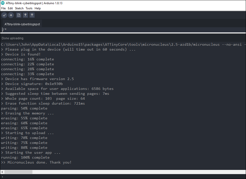
After the last step, you should see the messages as shown below and the LED on the Digispark ATtiny85 board should start blinking.
Important Notes on Digispark ATtiny85 I/O Ports
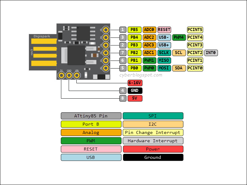
According to specifications, Digispark ATtiny85 boards support a total of six (6) digital I/O ports. However, there are several points to consider. Please refer to the Digispark ATtiny85 pinout in Figure 6.
- PB5 is by default being used as a Reset pin, hence, unavailable as a digital IO. ATtiny85 fuses have to be set to enable PB5 as an IO port. Moreover, PB5, when used as an output port, have some peculiarities. When it is at output HIGH, its output is 3V instead of 5V. Aside from that, it has limited current sourcing capability unlike the other ports that can source up to 20 milliamperes (20mA).
- Either PB0 or PB1 is used by the built-in LED depending on the Digispark model. Model A uses PB1 while Model B uses PB0. The explanation can be found here: Digispark Model A vs Model B.
- PB3 is used as USB+ for USB communication and has a 1.5K pull-up resistor.
- PB4 is used as USB- also for USB communication.
How to Address or Reference Digispark ATtiny85 Ports in Program
When programming the Digispark ATtiny85 in Arduino IDE, references to the IO ports differ between digital IO and analog input. When using the ports as digital input or digital output, PB0 to PB5 are referred to by their port numbers. That is, PB0 is 0, PB1 is 1, PB2 is 2, PB3 is 3, PB4 is 4, and PB5 is 5. For example:
pinMode(0, INPUT);  //PB0 is input
pinMode(1, INPUT);  //PB1 is input
pinMode(2, INPUT);  //PB2 is input
pinMode(3, OUTPUT);  //PB3 is output
pinMode(4, OUTPUT);  //PB4 is output
pinMode(5, OUTPUT);  //PB5 is output
bool x,y,z;
x = digitalRead(0);  //read PB0
y = digitalRead(1);  //read PB1
z = digitalRead(2);  //read PB2
digitalWrite(3, HIGH);  //make PB3 HIGH
digitalWrite(4, HIGH);  //make PB4 HIGH
digitalWrite(5, LOW);  //make PB5 LOW
However, when the ports are used as analog input, the port references are different. Please refer to Digispark ATtiny85 pinout in Figure 6. There are only four (4) ports usable as ADC input. These are PB2, PB3, PB4, and PB5. Their corresponding ADC port numbers are ADC1, ADC3, ADC2, and ADC0. In other words,
- PB2 is ADC1
- PB3 is ADC3
- PB4 is ADC2
- PB5 is ADC0
As an example,
//pinMode() always refer to the Port B numbers
//applicable to both digital and analog I/O
pinMode(5, INPUT);  //Make PB5 as input (ADC0)
pinMode(2, INPUT);  //Make PB2 as input  (ADC1)
pinMode(4, INPUT);  //Make PB4 as input (ADC2)
pinMode(3, INPUT);  //Make PB3 as input (ADC3)
int a, b, c, d;
//Uses analog port numbers instead of Port B numbers
a = analogRead(0);  //Read PB5
b = analogRead(1);  //Read PB2
c = analogRead(2);  //Read PB4
d = analogRead(3);  //Read PB3
Now, how about analogWrite()? Does it use the analog port numbers too? The answer is NO.
Again, referring to the Digispark ATtiny85 pinout above, there are three (3) ports capable of PWM outputs. These are PB0, PB1, and PB4. Let us look at an example of how to use them.
//all port references are Port B numbers like digitalRead() and digitalWrite()
pinMode(0, OUTPUT);
pinMode(1, OUTPUT);
pinMode(4, OUTPUT);
analogWrite(0, 255);  //100% duty cycle (fully on) PWM on PB0
analogWrite(1, 128);  //50% duty cycle PWM on PB1
analogWrite(4, 0);  //0% duty cycle (off) PWM on PB4
Summary on How to Address or Reference Digispark ATtiny85 Ports in Program
To summarize, the commands pinMode(), digitalRead(), digitalWrite(), and analogWrite() all use the Port B number references. Specifically, 0 for PB0, 1 for PB1, 2 for PB2, 3 for PB3, 4 for PB4, and 5 for PB5. However, as an exception, analogRead() uses its own ADC port numbers. Namely, 0 for PB5, 1 for PB2, 2 for PB4, and 3 for PB3.
References on How to Program Digispark ATtiny85 Board with Arduino IDE
How to Program ATtiny85 with Arduino IDE
Digispark USB Device Not Recognized
How to Enable Serial Monitor on Digispark ATtiny85
Digispark ATtiny85 Pinout and Configuration
How to Use AT-09 BLE with Arduino and Smartphone
Arduino IDE Download Page
ATtinyCore by SpenceKonde on Github
Digispark Model A Versus Model B