
When you buy a new ESP-01 ESP8266 module, the very first thing to do is to test it. That is, you need to make sure that you have a good and working ESP-01 module. We will take a look at the different methods of testing the ESP-01 ESP8266 Wi-Fi module.
Differences Between ESP-01 and ESP-01S ESP8266 Module
Before we proceed, be aware that there are two (2) versions of ESP-01 modules. The older ESP-01 module and the newer ESP-01S module. Both modules are functionally the same. However, there are two points worth mentioning here.
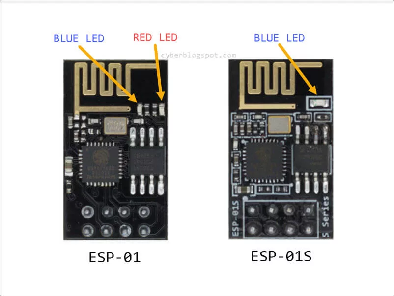
First, the ESP-01 has two (2) LEDs, a red LED power indicator and a blue LED that indicates serial activity. On the other hand, the newer ESP-01S has only one (1) LED, the blue LED light (see Figure 2 above). Moreover, the blue LED serial activity indicator light is wired differently on each module. That is, on an ESP-01 module, it is connected on the TX pin (GPIO1) while on the ESP-01S module, it is connected on the GPIO2 pin. And as a side note, pins GPIO0 and GPIO1 are both serial TX capable pins (refer to the ESP-01S schematic diagram at the end of this article).
Second, the ESP-01S module has three (3) additional on-board resistors used as pull-up resistors. These pull-up resistors are 12K-ohm resistors each connected on the GPIO0, the RESET, and the CH_PD pins. You may also want to refer again to the ESP-01S schematic diagram included at the end of this article.
Quick and Dirty Test
The ESP-01 module is shipped with a program called AT firmware. The firmware will let you send AT commands to configure and program the module. More important, the module is configured as a Wi-Fi Access Point (AP) when shipped. Therefore, a quick and dirty test is to power the ESP-01 module and use a smartphone to connect to the Access Point.
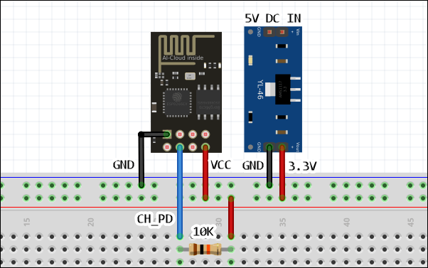
Power up the ESP-01 module as shown in Figure 3. Notice that we need to connect the ESP-01 module to a 3.3V power supply. Do not connect the ESP-01 module to the 3.3V output of an Arduino board. Provide a separate 3.3V power supply with sufficient current capacity. Also, note that a 10K ohms resistor is connected from the CH_PD pin to the VCC or the 3.3V supply. The CH_PD (Chip Power Down / Enable Pin) pin has to be pulled up to the VCC for the module to function. If you have the ESP-01S module, you do not need to connect a 10K ohm resistor on the CH_PD pin. As per discussion above on the differences between the ESP-01 and the ESP-01S modules, the ESP-01S already has a 12K-ohm pull-up resistor on the CH_PD pin.
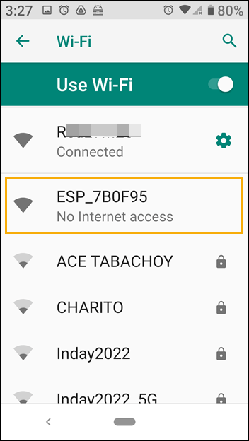
After powering up, you should see the ESP-01 access point when you scan for Wi-Fi devices. The default SSID of the ESP-01 module I am using is ESP_7B0F95. See Figure 4.
Connect to the ESP-01 Access Point.
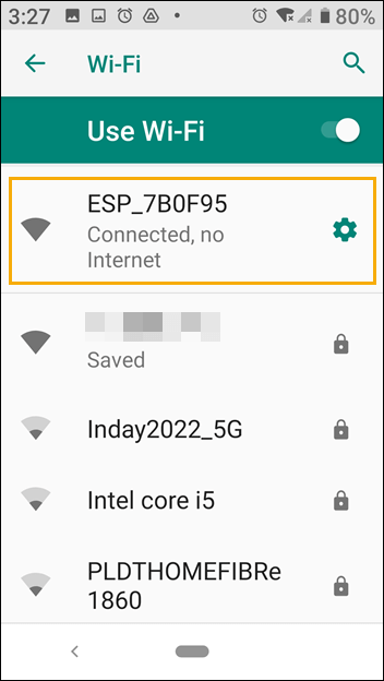
Click on the Settings icon (gear icon) and see the network details of the ESP-01 module Access Point.
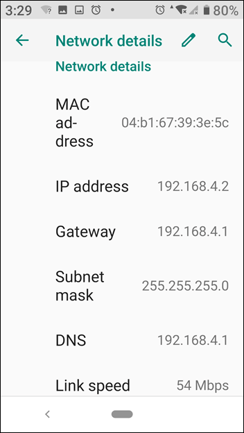
AT Command Test
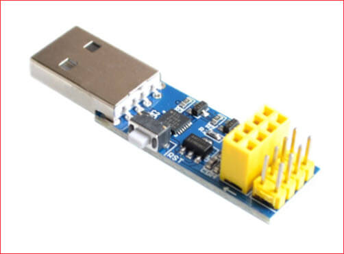
For the next test, you need an ESP-01 programmer or flasher. An inexpensive programmer/flasher is shown below in Figures 7. In Figure 8, the ESP-01 module is shown inserted into the programmer/flasher. If you do not have a programmer/flasher, it is possible to use an Arduino board as a programmer/flasher. Also, if you have a USB-to-serial(TTL) converter, you could wire it up as an ESP-01 programmer/flasher.
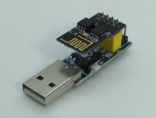
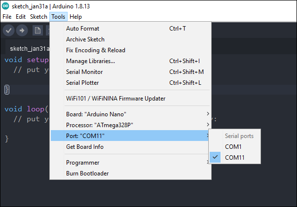
Insert the ESP-01 module to the programmer as shown in Figure 8 and plug the programmer to the computer. If it is your first time to use your programmer/flasher, you may have to install its device driver. Open the Arduino IDE and set the appropriate COM port for your programmer (Figure 9). For the meantime, there is no need to set the Board type.
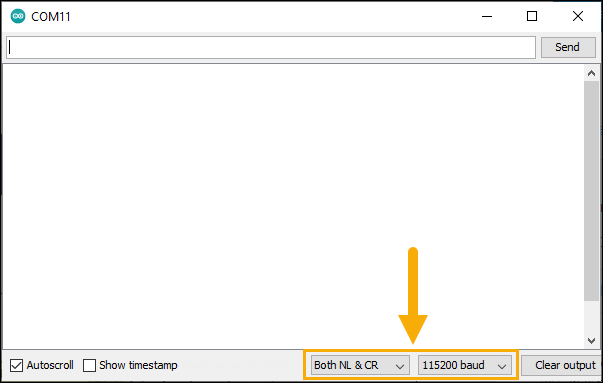
Open the Serial Monitor and change the settings as shown in Figure 10. The line ending setting must be set to both newline and carriage return, “Both NL & CR”. Additionally, the baud rate setting must be set to “115200 baud”.
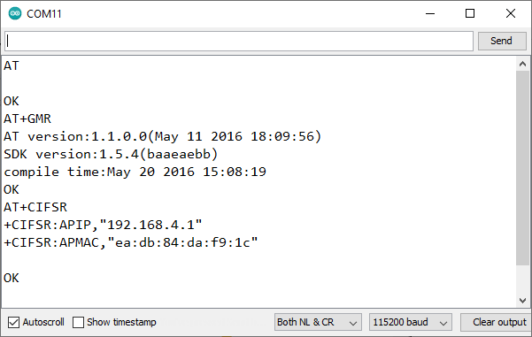
Now type “AT”, press the return key and the ESP-01 module should reply “OK”.
To view the ESP-01 module firmware version, type “AT+GMR”.
Type “AT+CIFSR” to view the Access Point’s IP address and network MAC address. See Figure 11 for the output display.
For a complete guide on the ESP-01 module AT commands, see ESP8266 – AT Command Reference.
Programming with Arduino IDE
In the next test, we will upload a modified version of the sample sketch Blink from the Arduino IDE. The sketch should make the blue LED on the ESP-01 module turn on and off.
IMPORTANT
Uploading an Arduino sketch to the ESP-01 module will erase the AT firmware. The AT commands will not work anymore after the upload. If you want to be able to restore the original firmware, please see the article
How to Save and Restore ESP8266 and ESP32 Firmware.
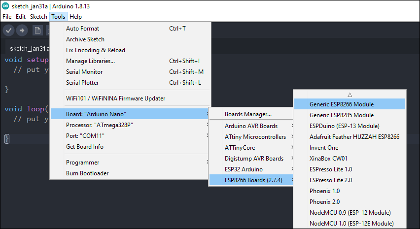
With the ESP-01 module still in the programmer/flasher, open the Arduino IDE and change the Board setting to “Generic ESP8266 Module” as shown in Figure 12.
Create a new sketch, copy and paste the blink program shown below. Upload the sketch to the ESP-01 module. The blue LED should start blinking after successfully uploading the sketch.
/*
* cyberblogspot.com 01Feb2023
*/
#define LED_BUILTIN 1 // GPIO1 for ESP-01, GPIO2 for ESP-01S
// Change to 2 for ESP-01S module
void setup() {
pinMode(LED_BUILTIN, OUTPUT);
}
void loop() {
digitalWrite(LED_BUILTIN, LOW); // Turn the LED on (ESP-01 LED is active low)
delay(1000);
digitalWrite(LED_BUILTIN, HIGH); // Turn the LED off
delay(1000);
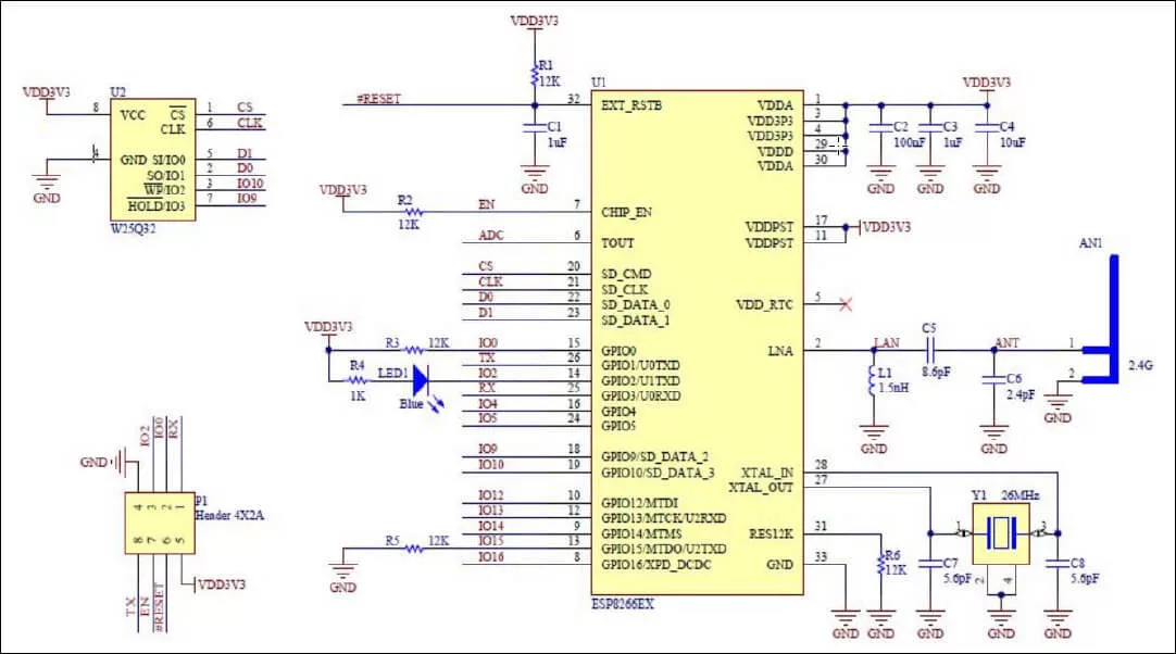
}Schematic Diagram of ESP-01S ESP8266 Wi-Fi Module
Related Articles on How to Test an ESP-01 ESP8266 Module
How to Set up Arduino IDE for ESP8266 Programming
How to Program ESP-01 with Arduino IDE
How to Control ESP-01 thru a Router
How to Control ESP-01 Without a Router
ESP-01 with RTC and LCD Display
ESP-01 ESP8266 NTP Clock with LCD Display
How to Test NodeMCU V3 Using Esptool
NodeMCU V3 ESP8266 Pinout and Configuration
How to Use AT-09 BLE with Arduino and Smartphone