When you need an accurate ADC for your Arduino, an ADS1220 ADC module is one viable solution. First, ADS1220 ADC modules or breakout boards use a precise 24-bit analog to digital converter. Second, these modules are widely available. As a matter of fact, there are many manufacturers of these boards. You can get them from Protocentral, Olimex and CJMCU, just to mention a few. Also, many online stores sell them, especially the CJMCU model. Third, besides precision and availability, some of these modules are very cheap. As an example, I bought my CJMCU ADS1220 ADC module for around US$5. And finally, if you have the proper tools and are able work with SMD chips, you can make your own DIY ADS1220 ADC module.
Introducing the ADS1220 Chip
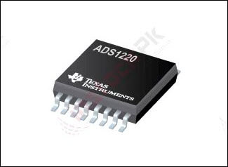
The heart of an ADS1220 ADC module is an ADS1220 chip. It is a precision 12-bit analog to digital converter (ADC) from TI or Texas Instruments. It has four (4) single-ended input channels. These channels can act as two (2) differential input channels. Also, it has a low-noise programmable gain amplifier (PGA). Furthermore, it offers two modes of conversion. That is, it can use either continuous conversion or single-shot conversion modes.
Notable Features of the ADS1220 Chip
- Four channel inputs (or two differential inputs)
- 24-bits resolution (20-bits ENOB or effective resolution)
- Low current consumption and wide power supply range
- Programmable gain amplifier and programmable data rates
- 50-Hz and 60-Hz noise rejection
- Low drift internal voltage reference and accurate internal oscillator
- Programmable current sources
- Internal temperature sensor
- SPI interface
- Available in small VQFN package
ADS1220 Chip Pinout
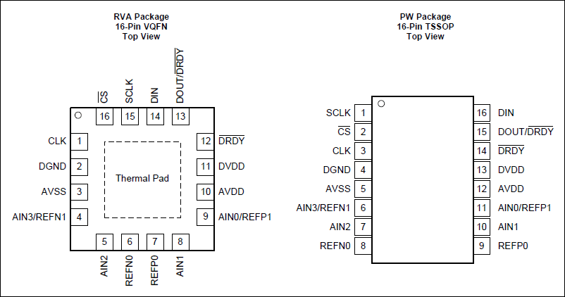
The figure above shows the pinouts of the two (2) ADS1220 integrated circuit packages. The 16-pin TSSOP (Thin Shrink Small Outline Package) package is the bigger of the two (2) packages. It has a chip body of around 5.1mm x 4.5mm. On the other hand, the VQFN (Quad Flatpack No-Lead) package has a very small 3.6mm x 3.6mm body dimension.
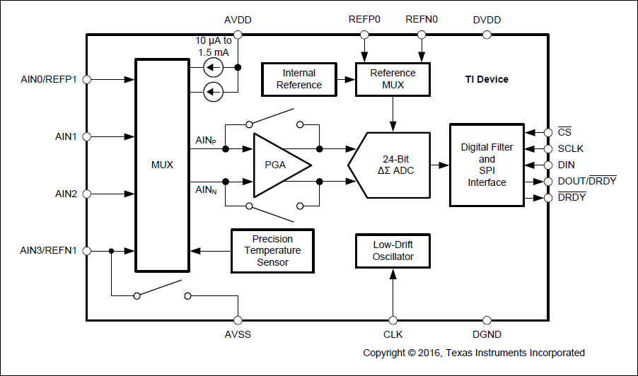
ADS1220 Chip Functional Block Diagram
Recommended SPI Connection to Microcontroller
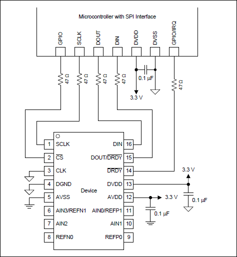
Shown above is the recommended wiring (datasheet page 43) for connecting the ADS1220 chip to a microcontroller. As you can see, they added series resistors on the SPI lines. If you intend to build your own ADS1220 ADC module or breakout board, you may consider using this schematic. Actually, the Protocentral ADS1220 breakout board closely resemble this schematic. In contrast, the Olimex ADS1220 module only added the decoupling capacitors on their board. We will take a look at the schematic of these modules later on.
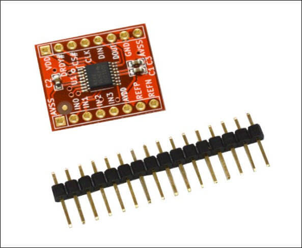
The ADS1220 ADC Module or Breakout Board for Arduino
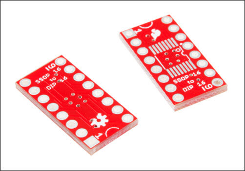
The ADS1220 chip comes in a very small package. That is, it is not available in a bigger DIP package that can be inserted on a breadboard. However, it is possible to solder an ADS1220 chip to a DIP adapter. So, some people buy the ADS1220 chip in a TSSOP package and solder it to a 16-pin DIP adapter board. Shown below is an example of an SSOP to DIP adapter from Sparkfun.
To make life easier for most of us, we can use instead ready made ADS1220 ADC modules or breakout boards. These modules come with the necessary resistors and capacitors already soldered in. For example, the Protocentral board (pictured below) comes with two decoupling capacitors. That is, one each for the analog and digital power supply lines. Also, they included three (3) series resistors on the SPI lines.
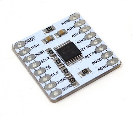
The ADS1220 ADC module above is from Protocentral. It is currently available on their online store for US$23.67.
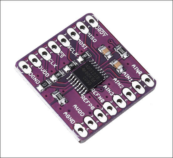
An ADS1220 ADC module for Arduino which is widely available is the CJMCU ADS1220 ADC module. At newegg, the module sells for US$13.89 while AliExpress sells it cheap. Only about US$4.20 for a piece.
ADS1220 ADC Module Schematic Diagram
Protocentral and CJMCU ADS1220 ADC Module Schematic Diagram
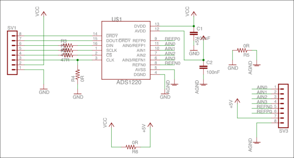
The screenshot above is the schematic diagram of a Protocentral’s ADS1220 ADC module. Although the CJMCU ADS1220 ADC modules use the same schematic, there is one difference. The CJMCU models use 24Ohms resistors on the SPI lines instead of the 47Ohms used by Protocentral.
Olimex ADS1220 ADC Module Schematic Diagram
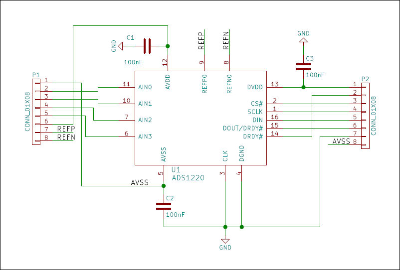
The schematic shown above is from an Olimex ADS1220 ADC module or breakout board. In contrast to the Protocentral and CJMCU modules, the Olimex version uses no resistors. However, it has the required decoupling capacitors for the power supplies. Also, take note that the Olimex model uses a 100nF capacitor to connect the analog and the digital ground. On the other hand, the other two (2) models use a 0Ohm resistor.
How to Connect ADS1220 ADC Module to Arduino
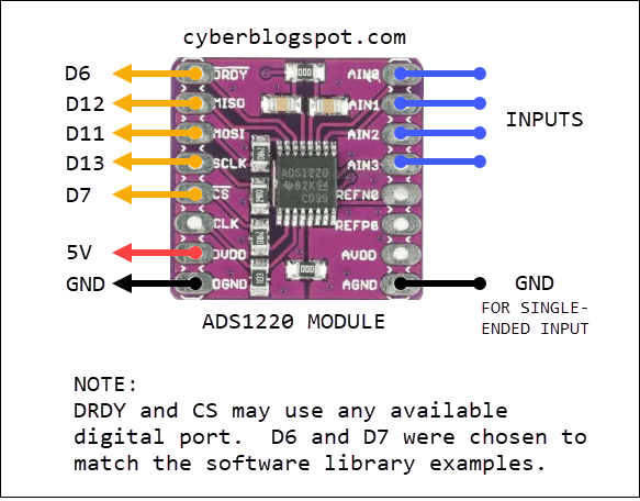
The SPI interface of the ADS1220 Module must be directly connected to the Arduino’s SPI pins (D11, D12 and D13). However, for the DRDY and CS pins, any available digital ports should pretty well work. As for me, I used D6 and D7 just to match the wiring diagram in the Arduino library.
| ADS1220 MODULE | ARDUINO |
|---|---|
| DRDY | D6 |
| MISO | D12 |
| MOSI | D11 |
| SCLK | D13 |
| CS | D7 |
| CLK | Not Connected |
| DVDD | 5V |
| DGND | GND |
For those who prefer a more graphical aids, here it is.
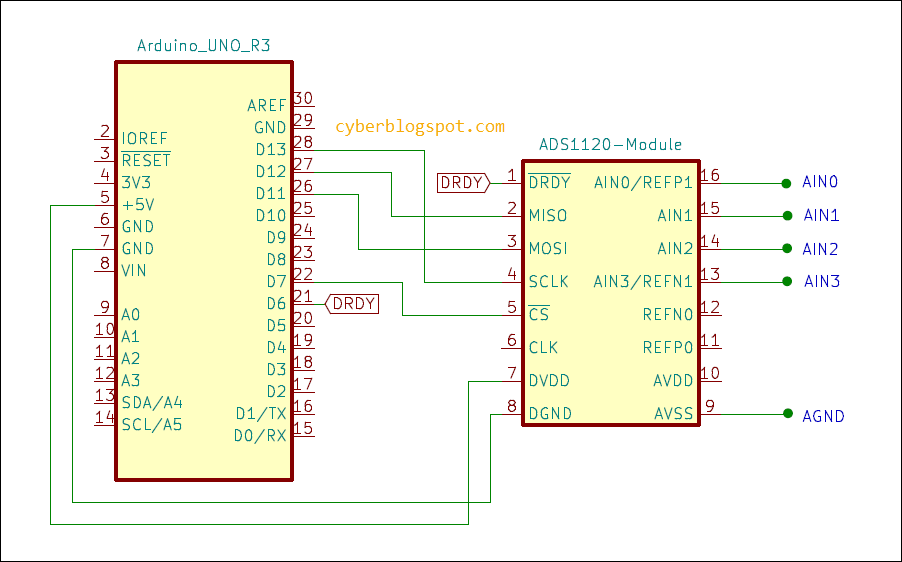
And of course, we still have the old school schematic diagram. This schematic was drawn using Kicad.
ADS1220 ADC Module Arduino Library
How to Install ADS1220 ADC Module Arduino Library
To program the ADS1220 ADC module in Arduino, you may use the Protocentral’s ADS1220 library. The library can be installed using the Arduino IDE Library Manager. First, click on “Tools” on the Arduino IDE’s main menu. Then, select “Manage Libraries”. On the “Library Manager” window, click on the textbox and type “ADS1220”. You should see the Protocentral library listed. Next, click the “Install” button to finally install the library.
Problem with the Protocentral Library Version 1.1.2
The latest version of the library, as of this writing, is Version 1.1.2. The library is fine and working as it should be. However, the two examples that comes with this version are pretty messed up.
The second example, aptly named Example2-ADS1220_Read_Stream.ino, has three (3) setup() procedures and three (3) loop() procedures. As a result, this example will not compile as it is. Actually, it is very easy to spot the problem. If you look at the sketch, you will see that it is made up of three copies of the same program. Therefore, to fix it, you simply delete the two extra copies. After that, the example will compile and run without any problem.
TO ERR IS HUMAN, but I think besides being reckless, it seems that the new library maintainer does not know what he/she is doing. Actually, the Example2-ADS1220_Read_Stream.ino is a modified version of the ADS_Read_Stream.ino that is on the previous library version 1.1.1. The previous example uses the Read_WaitForData() method to illustrate differential read on continuous conversion mode. Because this example uses a blocking method, the new maintainer modified it to instead use an interrupt. In this way, the program does not waste CPU cycles waiting for data during conversions. Very good, indeed. BUT by modifying the previous example, a good and working example was virtually obliterated.
What Should Have Been Done
WHAT SHOULD HAVE BEEN DONE WAS TO LEAVE THE PREVIOUS EXAMPLE ALONE. AND THEN, CREATED A NEW INTERRUPT-DRIVEN EXAMPLE IN A SEPARATE FILE!!! Instead of increasing the number of examples, what transpired was the deletion of one of the good examples.
Using the Protocentral ADS1220 Library
To use the Protocentral ADS1220 library, first, we must include the library header file.
#include "Protocentral_ADS1220.h"
Then, create an instant of the class.
Protocentral_ADS1220 myADC;
Afterwards, in the program setup(), initialize the ADS1220 ADC device. You must specify in the .begin() procedure the CS_and DRDY pin connections. For example, if you connected the ADC module’s CS pin to D7 and the DRDY pin to D6, you would use myADC.begin(7, 6).
void setup()
{
myADC.begin(7, 6);  //myADC.begin(CS_PIN, DRDY_PIN);
}
Running the method myADC.begin() initializes the ADS1220 with the following default settings.
- Input Multiplexer Configuration: AINP=AIN0 and AINN=AIN1 (See ADS1220 datasheet, page 40)
- Gain Configuration is 1 (1/2/4/8/16/32/64/128)
- Programmable Gain Amplifier (PGA) = Enabled (Enabled/Disabled)
- Data Rate is 20 SPS (20/45/90/175/330/600/1000 – Normal Operating Mode)
- Operating Mode is Normal (Normal/Duty-Cycle/Turbo)
- Conversion Mode is Continuous (Single-shot/Continuous)
- Temperature Sensor Mode is Off (On/Off)
- Burn-out Current Sources are Off (On/Off)
- Voltage Reference is Internal (Internal 2.048V/External REFP0-REFN0/External REFP1-REFN1/Analog Supply AVDD-AVSS)
- FIR Filter Configuration is 50&60Hz (No Rejection/50&60Hz/50Hz/60Hz)
- Low-Side Power Switch = Open (Always Open/Command-Controlled)
- IDAC Current Setting is Off (Off/10/50/100/250/500/1000/1500uA)
- IDAC1 Routing = Disabled (Disabled/AIN0/AIN1/AIN2/AIN3/REFP0/REFN0)
- IDAC2 Routing = Disabled (Disabled/AIN0/AIN1/AIN2/AIN3/REFP0/REFN0)
- DRDY Mode is DRDY Pin Only (DRDY Pin Only/Simultaneous DOUT/DRDY)
Protocentral ADS1220 Library READ Methods
Before we proceed to the loop() procedure, let us first take a look at the different READ options.
Conversion Mode
First, the ADS1220 has two modes of conversion. The Continuous mode and the Single-shot mode. In the Continuous mode, the ADC continuously samples and converts the selected input signals. But in Single-shot mode, it makes a one-time conversion only and goes into a power down mode.
Input Mode – Differential and Single-Ended
Second, the ADS1220 also has two modes of input signal processing. It measures the input signals either as differential or single-ended. In the differential mode, the ADC measures the difference between two input channels. However, in single-ended mode, it measures the input signal with respect to the analog ground (AVSS).
Therefore, it would be nice if we have four different methods for the four(4) different possible configurations. That is,
- Continuous mode, single-ended
- Continuous mode, differential
- Single-shot, single-ended
- Single-shot, differential
Available READ Methods
In the latest Protocentral library, Version 1.1.2, there are four (4) read methods available. They are:
- Read_WaitForData()
- Read_SingleShot_WaitForData()
- Read_SingleShot_SingleEnded_WaitForData(channel)
- Read_Data_Samples()
Read_WaitForData() – waits for the ADC to assert the DRDY (data ready) pin before reading the data registers. This will work on all the four (4) different modes.
Read_SingleShot_WaitForData() – this can be used for Single-shot Differential mode. The difference from the Read_WaitForData() is the addition of Start_Conv() command to wake the device up. This is because, in single-shot mode, the ADC1220 always goes into sleep mode.
Read_SingleShot_SingleEnded_WaitForData(channel) – this is clearly only for single-shot and single-ended mode. This method needs a channel argument. That is, the channel to be read must be specified.
Read_Data_Samples() – this looks like a misnomer. Although it is only reading a single conversion, it seems to imply multiple data samples are being fetched. It is basically the same as Read_WaitForData() with the waiting removed. Perhaps, a more suitable name for this procedure is Read_NoWait(). Unfortunately, this command is only for interrupt driven reads.
CONTINUOUS CONVERSION MODE
Now let’s continue with the loop() procedure for reading the ADS1220 module. First, let’s consider the continuous mode operation.
void loop(){
set_conv_mode_continuous();   //go into continuous mode conversion
select_mux_channels(channel); //choose channels to read

int32_t rawADC = Read_WaitForData(); //read ADC data registers
Serial.print(rawADC);                //print read data
}
The code above will work for both differential and single-ended mode. How does it know if we are doing a differential or single-ended read? It all depends on the channels being selected. If any two of the four input channels (AIN0 to AIN3) were selected, then we are doing a differential read. Otherwise, we are making a single-ended read. Furthermore, the channel parameter accepts the following pre-defined constants only.
DIFFERENTIAL INPUTS
MUX_AIN0_AIN1
MUX_AIN0_AIN2
MUX_AIN0_AIN3
MUX_AIN1_AIN2
MUX_AIN1_AIN3
MUX_AIN2_AIN3
MUX_AIN1_AIN0
MUX_AIN3_AIN2

SINGLE-ENDED INPUTS
MUX_AIN0_AVSS
MUX_AIN1_AVSS
MUX_AIN2_AVSS
MUX_AIN3_AVSS
MUX_SE_CH0
MUX_SE_CH1
MUX_SE_CH2
MUX_SE_CH3
SINGLE-SHOT CONVERSION MODE
The code for reading in single-shot mode is the same as above. The only difference is the changing of the conversion mode to single-shot. Also, as in continuous conversion mode, the channels selected determine whether it is differential or single-ended reading.
void loop(){
set_conv_mode_single_shot();   //go into single-shot mode conversion
select_mux_channels(channel);  //choose channels to read

int32_t rawADC = Read_WaitForData(); //read ADC data registers
Serial.print(rawADC);                //print read data
}
In single-shot conversion mode, we have two (2) additional read commands available. For differential mode we can use Read_SingleShot_WaitForData(). But the code is almost the same. In this case, though, there is no mistaking that we are doing a single-shot read.
void loop(){
set_conv_mode_single_shot();   //go into single-shot mode conversion
select_mux_channels(channel);  //choose channels to read

int32_t rawADC = Read_SingleShot_WaitForData(); //read ADC data registers
Serial.print(rawADC);                           //print read data
}
However, the other option for reading a single-ended and single-shot mode has one advantage. We are able to save one line of code. Because we are specifying what channels to read, we don’t need to precede the reading with a channel change procedure.
void loop(){
set_conv_mode_single_shot();   //go into single-shot mode conversion
//select_mux_channels(channel);  //choose channels to read

int32_t rawADC = Read_SingleShot_SingleEnded_WaitForData(channel); //read ADC data
Serial.print(rawADC);                                              //print read data
}
Remember that we are doing a single-ended read. So, the only valid channel arguments are MUX_SE_CH0, MUX_SE_CH1, MUX_SE_CH2 and MUX_SE_CH3. Or its equivalent MUX_AINX_AVSS constants may be used.
The Programmable Gain Amplifier
The ADS1220 ADC converter has a programmable gain amplifier. It is used for changing the sensitivity of the ADC converter. Therefore, the Protocentral library has functions to turn it on and off. Also, a there is a useful function for changing the gain of the amplifier.
For switching the PGA on or off, we use the following functions:
void PGA_ON(void);
void PGA_OFF(void);
For changing the gain of the PGA, there is the set_pga_gain() function.
void set_pga_gain(int pgagain);
To change the gain of the PGA, we use the set_pga_gain(). The valid parameter values are shown below. The default PGA gain is 1. That is, if you do not like to increase the gain, you don’t need to run the set_pga_gain().
PGA_GAIN_1
PGA_GAIN_2
PGA_GAIN_4
PGA_GAIN_8
PGA_GAIN_16
PGA_GAIN_32
PGA_GAIN_64
PGA_GAIN_128
PGA, FSR, and VREF (Voltage Reference)
The PGA gain is related to the FSR (full-scale-reading) of the ADC1220. The table below shows the resulting FSR for each PGA gain settings. For example, if we set the gain to 1, the FSR is at its maximum of 2.048V. In contrast, setting the gain to the maximum value of 128 reduces the FSR to minimum 16mV.
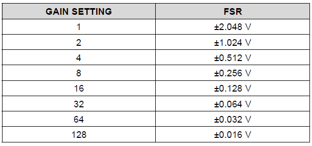
The FSR values in the table are only true if we are using the internal voltage reference, which is 2.048V. Otherwise, using an external reference with a different value will change the FSR. That is, the FSR is a function of the gain setting and the voltage reference. The formula for FSR is VREF/Gain.
To increase the FSR, we can use a higher voltage reference. For example, if we connect the pins REFP0 and REFN0 to a 5-volt voltage reference while our gain setting remains at 1, the FSR becomes 5V.
Converting ADC Values to Voltage
After reading the ADC digital output value, we need to convert it to a voltage value. The formula is:
Voltage = n * VREF / Gain / 8,388,607
where n is the int32_t value returned by the read command. VREF is the voltage reference in use. Finally, the Gain is the gain setting of the PGA.
How did we come up with the voltage formula?
In any ADC converter, the voltage is computed by multiplying the digital output n with the voltage reference value (VREF) and then divided by ADC resolution (the number of bits minus 1). For example, in Arduino Uno, the default voltage reference is 5V. The ADC converter has 10 bits of resolution. So, if we get a reading n from the ADC converter, the voltage is computed like this:
Voltage = n * VREF / 1023. Or, Voltage = n * 5V / 1023.
The divisor 1023 being (2^10)-1. That is, 2 raised to the exponent of the resolution (10) minus 1.
In the same way, the ADS1220 ADC has a default voltage reference (VREF) of 2.048V. Also, the ADS1220 ADC has a 24-bit resolution. But unlike the Arduino Uno, the ADS1220 can measure negative voltages. Hence, one of the bits in the 24-bit register is used for storing the polarity (negative/positive). As a result, we are left with only 23 bits of resolution. And this resolution is (2^23)-1. This is equal to 8,388,607.
Default PGA = 1
Let’s assume that the gain setting of the PGA is 1. In this way, we can disregard the Gain in the computation. Therefore, as in Arduino Uno, the voltage formula for the ADS1220 is:
Voltage = n * VREF / 8,388,607. Or Voltage = n * 2.048V /8,388,607.
Now, let’s factor in the Gain of the PGA. For example, let’s say we increase the gain to 2. The PGA doubles the amplitude of the input voltage before feeding it to the ADC converter. Therefore, the value being measured by the ADC converter is twice the real voltage. As a result, the digital output n from the ADC converter has to be divided by 2 to get the original voltage. In short, any gain that is applied to the PGA has to be divided from the digital output of the ADC (n / Gain). That leads us to the formula,
Voltage = n / Gain * VREF / 8,288,607. Or Voltage = n * VREF / Gain / 8,288,607.
The reason for the equivalence of the above formula is in the precedence rule. In multiplication and division, it does not matter whichever comes first. In other words, multiplication and division have the same precedence rank.
Changing the Data Rate
The ADS1220 can be programmed to operate with different data rates. Data rates can be set from 20 SPS (Samples Per Second) to 1000 SPS. The function for this is the set_data_rate(SPS). The valid arguments for the SPS are shown in the list below. For example, to set the data rate to the maximum value of 1000 SPS, we call the command set_data_rate(DR_1000SPS).
DR_20SPS
DR_45SPS
DR_90SPS
DR_175SPS
DR_330SPS
DR_600SPS
DR_1000SPS
The Protocentral Library Examples
The following three(3) examples illustrate how to use the ADS1220 ADC module in Arduino. I took the first two examples from the older library version, version 1.1.1. However, the third example is from the latest library, version 1.1.2.
First Example – ADS1220_Read_Sequential.ino (From Library Version 1.1.1)
This example was lifted from the older version 1.1.1 and not the erroneously modified 1.1.2. The example uses the Read_SingleShot_SingleEnded_WaitForData() procedure.
First, at the setup() procedure, it changes the data rate to 330 SPS and sets the PGA gain to 1. Then, it switches to single-shot conversion mode. Afterwards, at the loop() procedure, it reads channel 0 and computes the voltage. It then prints the computed voltage to the serial monitor. After that, it does the same for the rest of the channels (1, 2 and 3).
//////////////////////////////////////////////////////////////////////////////////////////
//
//    Demo code for the ADS1220 24-bit ADC breakout board
//
//    Author: Ashwin Whitchurch
//    Copyright (c) 2018 ProtoCentral
//
//    This example sequentially reads all 4 channels in continuous conversion mode
//
//    Arduino connections:
//
//  |ADS1220 pin label| Pin Function         |Arduino Connection|
//  |-----------------|:--------------------:|-----------------:|
//  | DRDY            | Data ready Output pin|  D6              |
//  | MISO            | Slave Out            |  D12             |
//  | MOSI            | Slave In             |  D11             |
//  | SCLK            | Serial Clock         |  D13             |
//  | CS              | Chip Select          |  D7              |
//  | DVDD            | Digital VDD          |  +5V             |
//  | DGND            | Digital Gnd          |  Gnd             |
//  | AN0-AN3         | Analog Input         |  Analog Input    |
//  | AVDD            | Analog VDD           |  -               |
//  | AGND            | Analog Gnd           |  -               |
//
//    This software is licensed under the MIT License(http://opensource.org/licenses/MIT).
//
//   THE SOFTWARE IS PROVIDED "AS IS", WITHOUT WARRANTY OF ANY KIND, EXPRESS OR IMPLIED, INCLUDING BUT
//   NOT LIMITED TO THE WARRANTIES OF MERCHANTABILITY, FITNESS FOR A PARTICULAR PURPOSE AND NONINFRINGEMENT.
//   IN NO EVENT SHALL THE AUTHORS OR COPYRIGHT HOLDERS BE LIABLE FOR ANY CLAIM, DAMAGES OR OTHER LIABILITY,
//   WHETHER IN AN ACTION OF CONTRACT, TORT OR OTHERWISE, ARISING FROM, OUT OF OR IN CONNECTION WITH THE
//   SOFTWARE OR THE USE OR OTHER DEALINGS IN THE SOFTWARE.
//
//   For information on how to use, visit https://github.com/Protocentral/Protocentral_ADS1220
//
/////////////////////////////////////////////////////////////////////////////////////////

#include "Protocentral_ADS1220.h"
//#include <SPI.h>

#define PGA          1                 // Programmable Gain = 1
#define VREF         2.048            // Internal reference of 2.048V
#define VFSR         VREF/PGA
#define FULL_SCALE   (((long int)1<<23)-1)

#define ADS1220_CS_PIN    7
#define ADS1220_DRDY_PIN  6

Protocentral_ADS1220 pc_ads1220;
int32_t adc_data;

void setup()
{
    Serial.begin(9600);

    pc_ads1220.begin(ADS1220_CS_PIN,ADS1220_DRDY_PIN);

    pc_ads1220.set_data_rate(DR_330SPS);
    pc_ads1220.set_pga_gain(PGA_GAIN_1);

    pc_ads1220.set_conv_mode_single_shot(); //Set Single shot mode
}

void loop()
{
    adc_data=pc_ads1220.Read_SingleShot_SingleEnded_WaitForData(MUX_SE_CH0);
    Serial.print("\n\nCh1 (mV): ");
    Serial.print(convertToMilliV(adc_data));
    delay(100);

    adc_data=pc_ads1220.Read_SingleShot_SingleEnded_WaitForData(MUX_SE_CH1);
    Serial.print("\nCh2 (mV): ");
    Serial.print(convertToMilliV(adc_data));
    delay(100);

    adc_data=pc_ads1220.Read_SingleShot_SingleEnded_WaitForData(MUX_SE_CH2);
    Serial.print("\nCh3 (mV): ");
    Serial.print(convertToMilliV(adc_data));
    delay(100);

    adc_data=pc_ads1220.Read_SingleShot_SingleEnded_WaitForData(MUX_SE_CH3);
    Serial.print("\nCh4 (mV): ");
    Serial.print(convertToMilliV(adc_data));
    delay(100);
}

float convertToMilliV(int32_t i32data)
{
    return (float)((i32data*VFSR*1000)/FULL_SCALE);
}
Output of Example 1
Shown below is the output of the sketch above. First, take note that the configuration register values are printed at the start of the program. The ADC1220 chip has four(4) configuration registers. Therefore, the printed values 0, 4, 10, and 0 are the values of each of the four registers.
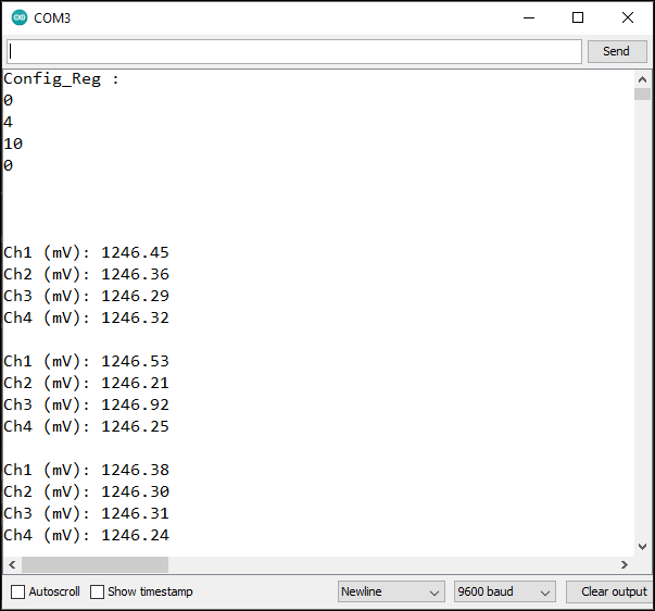
Second, look at the printed output voltage readings. Since I wired all the input channels to a single voltage, we should get four (4) identical readings. My digital multimeter is reading the voltage at 1.247V. I think this is impressive because the voltage is only fluctuating between 1246.21 and 1246.91 mV. Besides being very close to my DMM reading, the sketch is not even averaging the results. That is, it is promising that the ADS1220 ADC module could be even more precise with averaging and software calibration. Also, this should be more precise in differential mode where some of the noise can somehow be cancelled.
Second Example – ADS1220_Stream.ino (From Library Version 1.1.1)
This example was lifted from the old library version. Because in the latest version (1.1.2), the contents of this file were replaced by another example – an interrupt-based reading operation. We will take it up as another example next.
This example illustrates how to place the converter into continuous conversion mode. That explains the word “stream” in the filename. Then, it reads the input in differential mode. Also, it uses a different read function, the Read_WaitForData(). The sketch continuously reads the difference of channels 0 and 1 and prints the computed voltage value along with the raw ADC values from the converter.
Errata
This example sketch will run but it will give you a wrong voltage value. As previously discussed above, the voltage is computed by the following formula: Voltage = n * VREF / Gain / 8,288,607. Of course the sketch uses a similar formula. But at the start of the program, the Gain was defined as 1.
#define PGA 1                 // Programmable Gain = 1
#define VREF 2.048            // Internal reference of 2.048V
#define VFSR VREF/PGA
#define FSR (((long int)1<<23)-1)
Subsequently, in the setup() procedure, the gain setting was changed to 32.
pc_ads1220.set_pga_gain(PGA_GAIN_32);
Finally, in the loop() procedure, the voltage was computed.
float Vout = (float)((adc_data*VFSR*1000)/FSR); //In mV
Since the formula uses the variable VFSR which is defined as VREF/PGA and PGA is equal to 1, it will produce a wrong voltage value. This is because the PGA has been changed to 32.
To fix the problem, change #define PGA 1 to #define PGA 32. Or change the PGA_GAIN_32 argument to PGA_GAIN_1 in the call to set_pga_gain(). In other words, the PGA define directive has to match with the set_pga_gain() argument.
//////////////////////////////////////////////////////////////////////////////////////////
//
//    Demo code for the ADS1220 24-bit ADC breakout board
//
//    Author: Ashwin Whitchurch
//    Copyright (c) 2018 ProtoCentral
//
//    This example gives differential voltage across the AN0 and AN1 pins in mVolts
//
//    Arduino connections:
//
//  |ADS1220 pin label| Pin Function         |Arduino Connection|
//  |-----------------|:--------------------:|-----------------:|
//  | DRDY            | Data ready Output pin|  D6              |
//  | MISO            | Slave Out            |  D12             |
//  | MOSI            | Slave In             |  D11             |
//  | SCLK            | Serial Clock         |  D13             |
//  | CS              | Chip Select          |  D7              |
//  | DVDD            | Digital VDD          |  +5V             |
//  | DGND            | Digital Gnd          |  Gnd             |
//  | AN0-AN3         | Analog Input         |  Analog Input    |
//  | AVDD            | Analog VDD           |  -               |
//  | AGND            | Analog Gnd           |  -               |
//
//    This software is licensed under the MIT License(http://opensource.org/licenses/MIT).
//
//   THE SOFTWARE IS PROVIDED "AS IS", WITHOUT WARRANTY OF ANY KIND, EXPRESS OR IMPLIED, INCLUDING BUT
//   NOT LIMITED TO THE WARRANTIES OF MERCHANTABILITY, FITNESS FOR A PARTICULAR PURPOSE AND NONINFRINGEMENT.
//   IN NO EVENT SHALL THE AUTHORS OR COPYRIGHT HOLDERS BE LIABLE FOR ANY CLAIM, DAMAGES OR OTHER LIABILITY,
//   WHETHER IN AN ACTION OF CONTRACT, TORT OR OTHERWISE, ARISING FROM, OUT OF OR IN CONNECTION WITH THE
//   SOFTWARE OR THE USE OR OTHER DEALINGS IN THE SOFTWARE.
//
//   For information on how to use, visit https://github.com/Protocentral/Protocentral_ADS1220
//
/////////////////////////////////////////////////////////////////////////////////////////

#include "Protocentral_ADS1220.h"
#include <SPI.h>

#define PGA 1                 // Programmable Gain = 1
#define VREF 2.048            // Internal reference of 2.048V
#define VFSR VREF/PGA
#define FSR (((long int)1<<23)-1)

#define ADS1220_CS_PIN    7
#define ADS1220_DRDY_PIN  6

Protocentral_ADS1220 pc_ads1220;
int32_t adc_data;

void setup()
{
    Serial.begin(9600);

    pc_ads1220.begin(ADS1220_CS_PIN,ADS1220_DRDY_PIN);

    pc_ads1220.set_data_rate(DR_330SPS);
    pc_ads1220.set_pga_gain(PGA_GAIN_32);
    pc_ads1220.select_mux_channels(MUX_AIN0_AIN1);  //Configure for differential measurement between AIN0 and AIN1

    pc_ads1220.Start_Conv();  //Start continuous conversion mode
}

void loop()
{
    adc_data=pc_ads1220.Read_WaitForData();

    float Vout = (float)((adc_data*VFSR*1000)/FSR);     //In  mV

    delay(300);

    Serial.print("Vout in mV : ");
    Serial.print(Vout);
    Serial.print("  32bit HEX : ");
    Serial.println(adc_data,HEX);
}
Output of Example 2
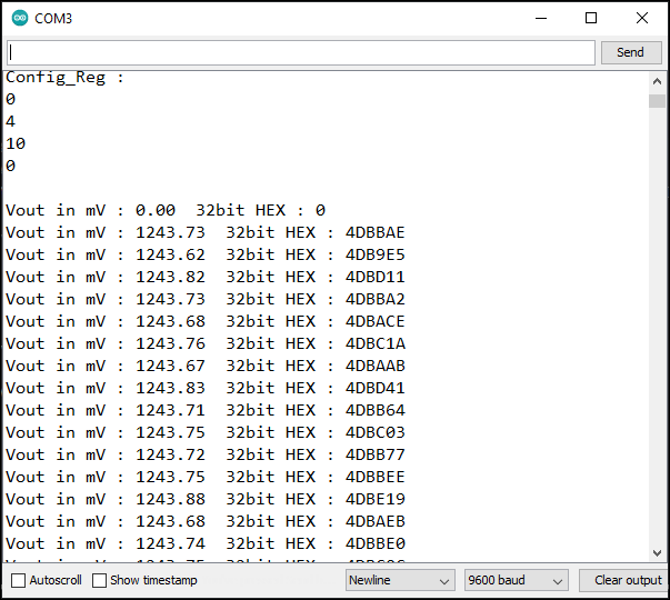
Here is the output for the sketch above. My DVM reading is 1.244 Volts. As I was expecting, because we’re in differential mode, the voltage fluctuations decreased. The voltage fluctuation is from 0.62 to 0.88 mV. That is, only 0.26 mV. In the previous example where the ADS1220 was in single-ended mode, the fluctuation was from 0.21 to 0.91mV. Or around 0.70 mV. So, there is a big reduction in the noise on the measured voltage.
Third Example – ADS1220_Stream.ino (From Library Version 1.1.2)
This third example should have been given a different filename. I think, a more suitable name is ADS1220_Interrupt.ino.
Errata
This example sketch suffers from the same error as in Example 2 above. The error has something to do with the voltage computation. That is, the PGA gain is defined with a value of 1 but the PGA gain was increased to 32. As a result, the voltage computation is wrong. Please see the preceding example.
How the sketch works
This example differs from the first two examples above. Examples 1 and 2 both use a read method that waits for the ADS1220 to assert the DRDY pin. That is, both methods goes into a loop checking the DRDY pin that indicates if a conversion data is available for reading. As a result, CPU time is wasted polling the DRDY pin. This example alleviates the problem by using a hardware interrupt.
First of all, take note that the DRDY pin of the ADS1220 ADC module was moved. That is, on the two (2) previous examples above, we connected the DRDY pin to Arduino pin D6. However, in this example, we need to connect the DRDY pin to Arduino pin D2. The reason for this is that, in Arduino Uno, by default, pins D2 and D3 are designated as interrupt pins.
//////////////////////////////////////////////////////////////////////////////////////////
//
//    Demo code for the ADS1220 24-bit ADC breakout board
//
//    Author: Ashwin Whitchurch
//    Copyright (c) 2018 ProtoCentral
//
//    This example gives differential voltage across the AN0 and AN1 pins in mVolts
//
//    Arduino connections:
//
//  |ADS1220 pin label| Pin Function         |Arduino Connection|
//  |-----------------|:--------------------:|-----------------:|
//  | DRDY            | Data ready Output pin|  D02             |
//  | MISO            | Slave Out            |  D12             |
//  | MOSI            | Slave In             |  D11             |
//  | SCLK            | Serial Clock         |  D13             |
//  | CS              | Chip Select          |  D7              |
//  | DVDD            | Digital VDD          |  +5V             |
//  | DGND            | Digital Gnd          |  Gnd             |
//  | AN0-AN3         | Analog Input         |  Analog Input    |
//  | AVDD            | Analog VDD           |  -               |
//  | AGND            | Analog Gnd           |  -               |
//
//    This software is licensed under the MIT License(http://opensource.org/licenses/MIT).
//
//   THE SOFTWARE IS PROVIDED "AS IS", WITHOUT WARRANTY OF ANY KIND, EXPRESS OR IMPLIED, INCLUDING BUT
//   NOT LIMITED TO THE WARRANTIES OF MERCHANTABILITY, FITNESS FOR A PARTICULAR PURPOSE AND NONINFRINGEMENT.
//   IN NO EVENT SHALL THE AUTHORS OR COPYRIGHT HOLDERS BE LIABLE FOR ANY CLAIM, DAMAGES OR OTHER LIABILITY,
//   WHETHER IN AN ACTION OF CONTRACT, TORT OR OTHERWISE, ARISING FROM, OUT OF OR IN CONNECTION WITH THE
//   SOFTWARE OR THE USE OR OTHER DEALINGS IN THE SOFTWARE.
//
//   For information on how to use, visit https://github.com/Protocentral/Protocentral_ADS1220
//
/////////////////////////////////////////////////////////////////////////////////////////

#include "Protocentral_ADS1220.h"
#include <SPI.h>

#define PGA 1                 // Programmable Gain = 1
#define VREF 2.048            // Internal reference of 2.048V
#define VFSR VREF/PGA
#define FSR (((long int)1<<23)-1)

#define ADS1220_CS_PIN    7
#define ADS1220_DRDY_PIN  2

Protocentral_ADS1220 pc_ads1220;
int32_t adc_data;
volatile bool drdyIntrFlag = false;

void drdyInterruptHndlr(){
  drdyIntrFlag = true;
}


void enableInterruptPin(){

 attachInterrupt(digitalPinToInterrupt(ADS1220_DRDY_PIN), drdyInterruptHndlr, FALLING);
}

void setup()
{
    Serial.begin(57600);

    pc_ads1220.begin(ADS1220_CS_PIN,ADS1220_DRDY_PIN);

    pc_ads1220.set_data_rate(DR_330SPS);
    pc_ads1220.set_pga_gain(PGA_GAIN_32);
    pc_ads1220.select_mux_channels(MUX_AIN0_AIN1);  //Configure for differential measurement between AIN0 and AIN1

    pc_ads1220.Start_Conv();  //Start continuous conversion mode

    enableInterruptPin();
}

void loop()
{
    if(drdyIntrFlag){
        drdyIntrFlag = false;

        adc_data=pc_ads1220.Read_Data_Samples();
        float Vout = (float)((adc_data*VFSR*1000)/FSR);     //In  mV

        delay(300);

        Serial.print("Vout in mV : ");
        Serial.print(Vout);
        Serial.print("  32bit HEX : ");
        Serial.println(adc_data,HEX);
    }
}
Output of Example 3
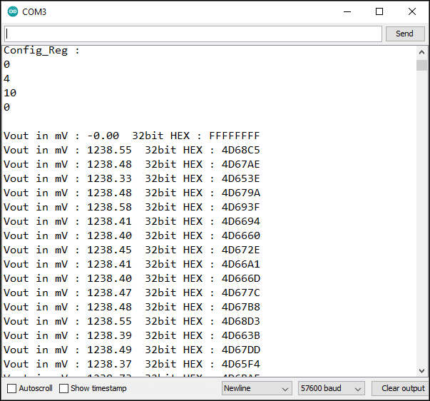
Those are all the examples that come with the Protocentral ADS1220 Library that we can use with the ADS1220 ADC module and Arduino. After publishing this article, I will be examining the other available ADS1220 libraries that are available in github. Then, maybe, if I find something useful, I will include them here later on.
Protocentral Library Version 1.1.2 Public Methods (List of All the Commands)
Below is an excerpt from the header file, Protocentral_ADS1220.h. Listed are all the different methods available for use. I rearranged it in order to group the related methods. Because some of the methods don’t exist in the Protocentral_ADS1220.cpp anymore, I placed them at the end of the list. That is, I leave them there for reference purposes.
Protocentral_ADS1220();
void writeRegister(uint8_t address, uint8_t value);
uint8_t readRegister(uint8_t address);
uint8_t * get_config_reg(void);

void begin(uint8_t cs_pin, uint8_t drdy_pin);

void SPI_Command(unsigned char data_in);
void ads1220_Reset(void);
void Start_Conv(void);

void PGA_ON(void);
void PGA_OFF(void);
void set_pga_gain(int pgagain);
void set_data_rate(int datarate);
void set_conv_mode_single_shot(void);
void set_conv_mode_continuous(void);
void select_mux_channels(int channels_conf);

int32_t Read_WaitForData();
int32_t Read_SingleShot_WaitForData(void);
int32_t Read_SingleShot_SingleEnded_WaitForData(uint8_t channel_no);
int32_t Read_Data_Samples();

//Don't exist in Protocentral_ADS1220.cpp
uint8_t * Read_Data(void);      //This has been removed, they forgot to delete
void Single_shot_mode_ON(void); //This has been removed, they forgot to delete
References on How to Use ADS1220 ADC Module with Arduino
ADS1220 Datasheet
Protocentral ADS1220 Library
Related Articles on How to Use ADS1220 ADC Module with Arduino
1 – How to Program ESP-01 with Arduino IDE
2- How to Install Esptool on Windows 10
3 – How to Save and Restore ESP8266 and ESP32 Firmware
4 – How to Test a NodeMCU V3 ESP8266 Dev Board
5 – NodeMCU V3 ESP8266 Pinout and Configuration
6 – NodeMCU ESP-32S Pin Configuration
7 – ESP-01 ESP8266 NTP Clock with LCD Display
8 – Arduino Auto Ranging Ohmmeter, Part 1
9 – How to Use MCP4725 Module with Arduino
Question: I am running a sketch derived from the Example – ADS1220_Stream.ino, and I would like to modify the gain between two adc_data=Read_Data_Samples(); by pc_ads1220.set_pga_gain(x); but this is not taken into account (Gain do not change). What have I to do ?
Regards,
Jean-Paul
Sorry, I just found my mistake: x had not the rigth format!
I am guessing that you did not use the right gain setting constant, that is, PGA_GAIN_X, where X is either 1, 2, 4, 8, 16, 32, 64, or 128.
Example:
pc_ads1220.set_pga_gain(PGA_GAIN_16); //set PGA gain to 16
Hello, thank you for the great explanation. Well written and detailed, learned a lot about how ads1220 works.
I’m new to using Arduino with ADS, and I’m sure I have made all the connection right, here’s the photo (https://share.siraj.ai/DOuDxEm6) of my setup but no matter what I get 0 voltage on console for all analog inputs. I have no idea why.
Can you please help?
Thanks in advance.
SCK is connected to GND. The wiring is wrong.
@Siraj Farhan,
I would like to help you but I have a hard time verifying if your wiring is correct. Could you draw a simple schematic of your connections? Also, post your sketch so we can see what is causing the problem.
“Data Rate is 20 SPS (20/45/90/175/330/600/1000 – Normal Operating Mode)
Operating Mode is Normal (Normal/Duty-Cycle/Turbo)”
Does the operating mode have anything to do with the max SPS? Specs say the ADS1220 can go as high as 2000SPS.
Hello,
Just a question please. How to change the voltage reference to an external voltage refrence?
You mentioned we need to connect the pins REFP0 and REFN0 to an external voltage reference while our gain setting remains at 1. However, it did not work?
Do I need to do changes with the code so it takes to account the external voltage refrence, not the enternal?
Many thanks in advance
How can I make ADS1220 to acquire samples with sampling rate of 2000SPS. Does Turbo mode relates to this setting