ISP (In-System Programming) programmers, which are also known as ICSP (In-Circuit Serial Programming) programmers, are used for burning bootloaders onto microcontroller (MCU) chips. They are also used for setting MCU chip fuses in order to change some of the chip’s functions. There are many cheap ISP programmers available on the internet. However, if you have an Arduino board (Arduino Uno, Nano, etc.) lying around, you do not need to buy an ISP programmer. You can easily turn an Arduino board into an ISP programmer. This article will show you how to use an Arduino board as an ISP programmer.
To use an Arduino board as an ISP programmer, simply upload the Arduino IDE example sketch named “ArduinoISP”. Next, connect the SPI pins of the Arduino board to the MCU chip or MCU board to be programmed. Then, you can start using the Arduino board as an ISP programmer.
To illustrate the steps for the procedure, first, I will make an Arduino Nano board into an ISP programmer. Then, I will show how to upload sketches and burn bootloaders to a Digispark ATtiny85 development board.
Step by Step Guide on How to Use Arduino as ISP Programmer
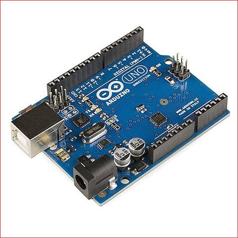
STEP 1 – Connect your Arduino board to your computer’s USB port.
Connect the Arduino board of your choice to your programming computer hosting the Arduino IDE. In the next several steps, we will upload the ArduinoISP sketch to the board to make it an ISP programmer.
STEP 2 – Open your Arduino IDE and open the ArduinoISP sketch.
Open your Arduino IDE. If you are a beginner and you have not yet installed the Arduino IDE, please see How to Install Arduino IDE on Windows 10. On the Main menu, select File/Examples/11.ArduinoISP/ArduinoISP.
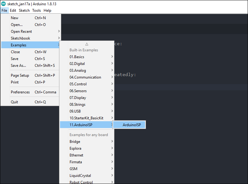
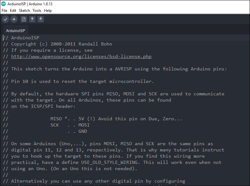
You should see the screen shown below after clicking on the ArduinoISP on the Built-in Examples menu.
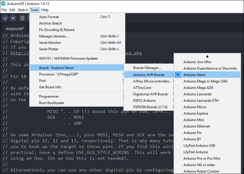
STEP 3 – Choose the name of your Arduino board from the Board Manager’s list.
Go to Tools/Board/Arduino AVR Boards and select the type of Arduino board you are using. As shown in the screenshot below, I chose Arduino Nano for my Arduino board.
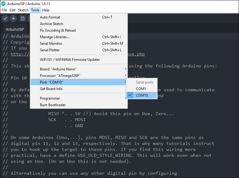
STEP 4 – Set the proper COM serial port for your board.
On the Tools menu, select Port. Then select from the serial ports list the appropriate port for your Arduino board.
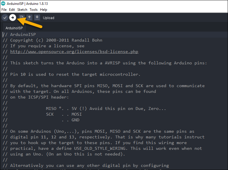
STEP 5 – Click the Upload button.
As a final step for uploading the ArduinoISP sketch to the Arduino board, click on the Upload button.
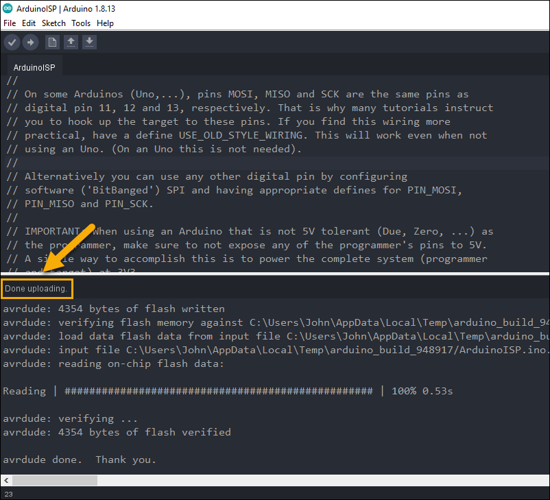
When you see the message “Done uploading”, congratulations!!! You now have a full-pledged ISP programmer.
In the following steps, we are going to show how to use the Arduino board acting as an ISP programmer to:
- Program or upload a sketch to a Digispark ATtiny85 board
- Burn an Optiboot bootloader
- Burn a Micronucleus bootloader
STEP 6 – Connect the ISP programmer (the Arduino board) to the Digispark ATtiny85 development board.
Like in any other ISP programmers, including the popular USBtinyISP and USBasp programmers, we use six (6) terminals of the ISP programmer to connect to the device to be programmed. These terminals are:
- MOSI
- MISO
- SCLK
- RESET
- VCC
- GND
On the Arduino board acting as an ISP programmer, the corresponding terminals are as follow:
- D11 (MOSI) —> MOSI
- D12 (MISO) —> MISO
- D13 (SCLK) —> SCLK
- D10 (SS) —> RESET
- 5V —> VCC
- GND —> GND
Now, based on the foregoing discussion, we can connect the Arduino board to the Digispark ATtiny85 board using the following terminals:
Arduino Board —> Digispark ATtiny85 Board
D11 (MOSI) —> PB0(MOSI)
D12 (MISO) —> PB1(MISO)
D13 (SCLK) —> PB2(SCLK)
D10 (SS) —> PB5(RESET)
5V —> 5V
GND —> GND
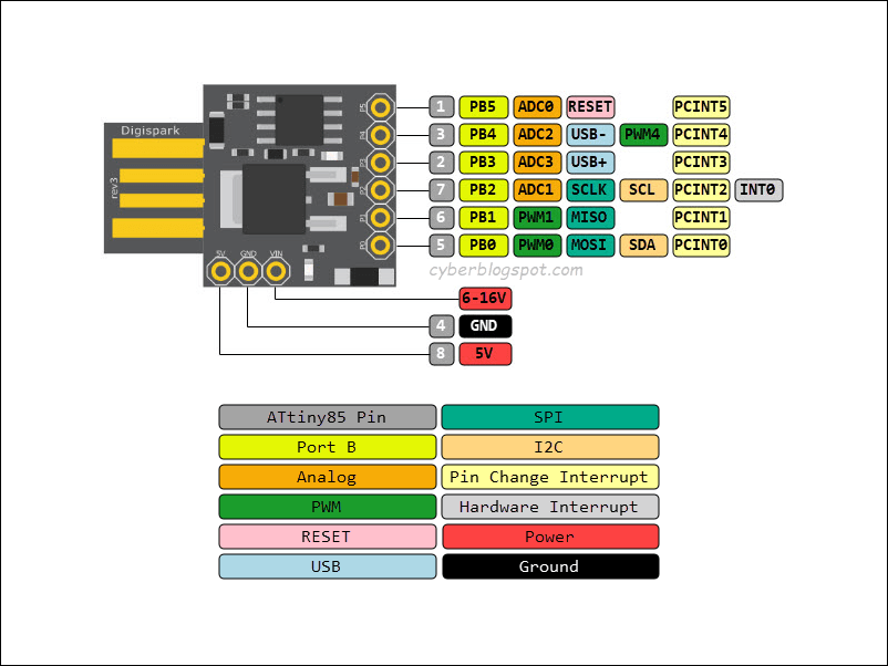
For reference purposes, the Digispark ATtiny85 development board pinout is shown below. For more information on Digispark ATtiny85, you may consult the Digispark ATtiny85 Pinout and Configuration.
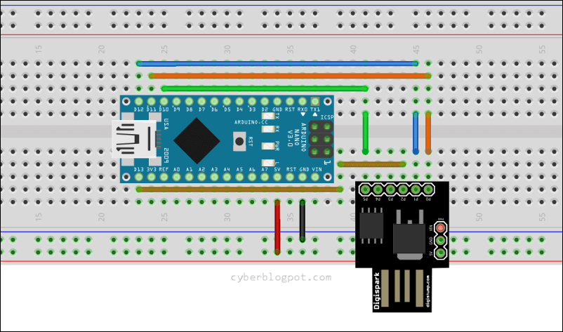
Shown below is the Fritzing breadboard diagram for connecting the Arduino Nano board to the Digispark ATtiny85 board.
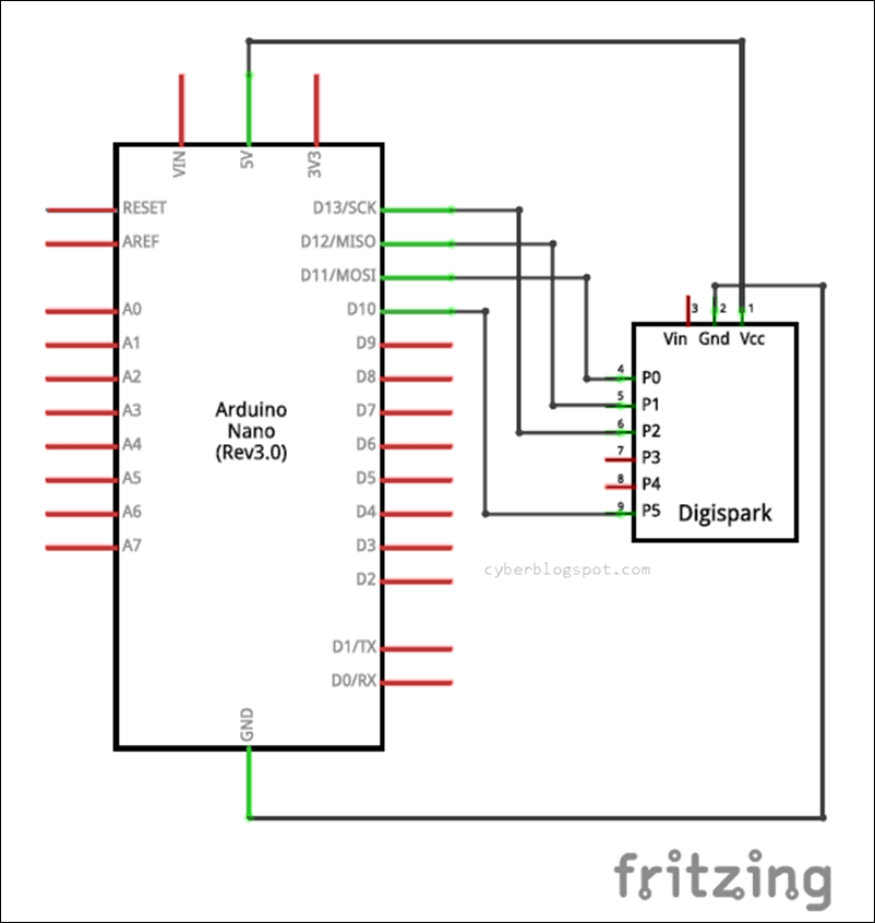
How to connect the Arduino Nano board to the Digispark ATtiny85 board illustrated by an old-school schematic diagram.
After connecting the Arduino board to the Digispark ATtiny85 board, we are now ready to test drive the Arduino board as an ISP programmer.
Since we are going to work with the Digispark ATtiny85 board, you must have the board core ATTinyCore by Spence Konde installed on your Arduino IDE. If you do not have the ATTinyCore installed yet, see the article How to Install ATTinyCore on Arduino IDE.
STEP 7 – Copy and Paste the Blink Program.
Going back to the Arduino IDE, create a new sketch and then copy and paste the Blink program sketch shown below.
/*
www.cyberblogspot.com
07Jan2022
*/
#define LED_BUILTIN 1 //PB1 for Model A
//PB0 for Model B
void setup() {
// initialize digital pin LED_BUILTIN as an output.
pinMode(LED_BUILTIN, OUTPUT);
}
// the loop function runs over and over again forever
void loop() {
digitalWrite(LED_BUILTIN, HIGH); // turn the LED on (HIGH is the voltage level)
delay(1000); // wait for a second
digitalWrite(LED_BUILTIN, LOW); // turn the LED off by making the voltage LOW
delay(1000); // wait for a second
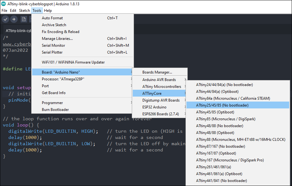
}STEP 8 – Change the board from Arduino board to Digispark ATtiny85 board.
Go to Tools/Board/ATTinyCore and select ATtiny25/45/85 (No bootloader). Take note that we are using the “No bootloader” option and NOT the “Micronucleus/Digispark” option. This is because we are going to upload the Blink sketch via an ISP programmer (the Arduino board) and not thru the Digispark’s USB port.
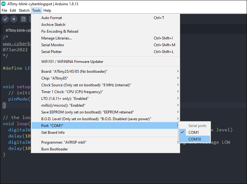
STEP 9 – Select the proper COM port.
Go to Tools/Port and choose the correct COM port from the ports list.
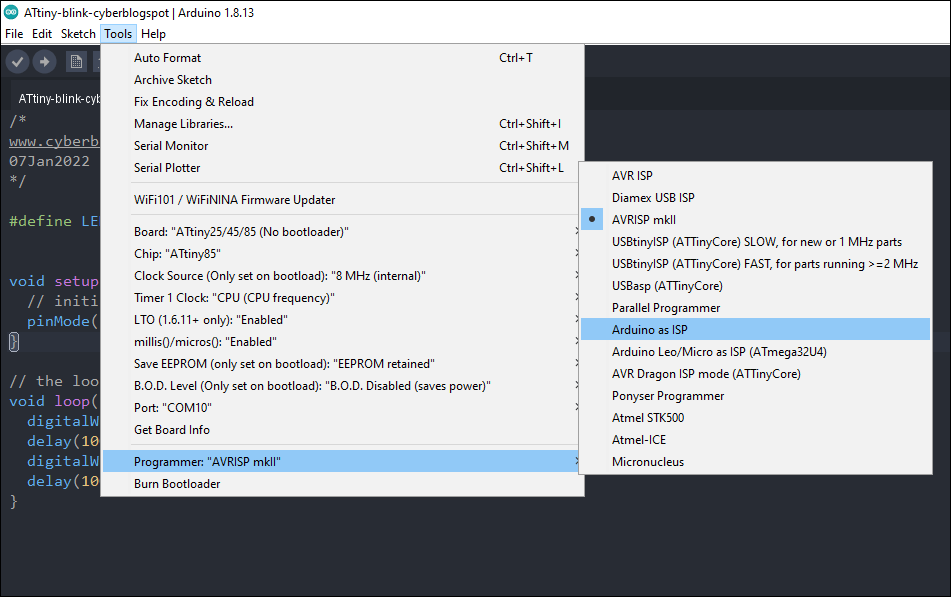
STEP 10 – Select the programmer type.
On the Tools/Programmer menu, select Arduino as ISP as the programmer type.
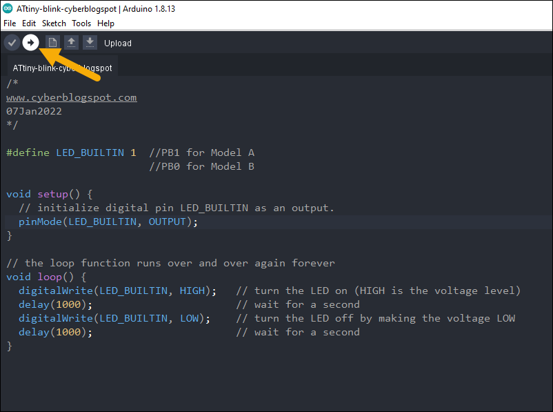
STEP 11 – Upload the Blink program.
Upload the Blink program by clicking on the Upload button.
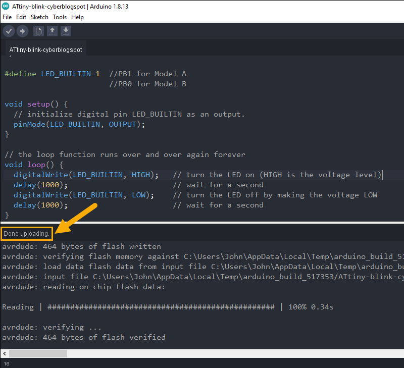
When you see the message saying that the upload is done, your Digispark ATtiny85 board should start blinking the built-in LED.
How to Burn Bootloader on Digispark ATtiny85 Using Arduino as ISP Programmer
Burn Optiboot Bootloader
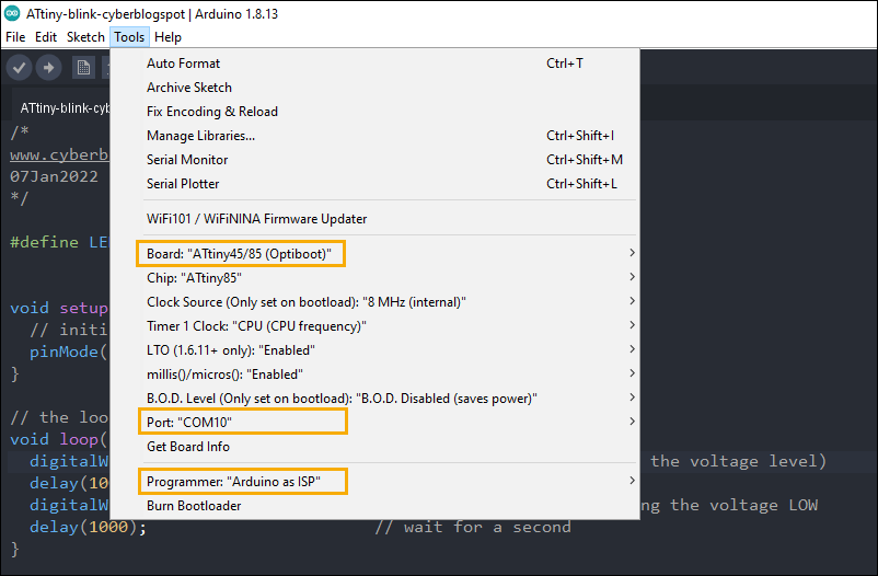
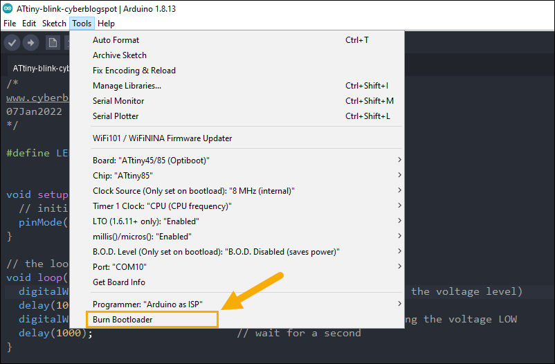
STEP 1 – Select ATtiny45/85 (Optiboot) from the ATtinyCore list.

STEP 2 – Verify that the proper COM port is selected.
STEP 3 – Make sure that the programmer selected is “Arduino as ISP”.
STEP 4 – Click “Burn bootloader” to start the burning process.
Burn Micronucleus Bootloader
To burn the Micronucleus bootloader onto the Digispark ATtiny85 board using the Arduino as ISP programmer, follow the steps above for burning the Optiboot bootloader. However, instead of selecting ATtiny45/85 (Optiboot), select ATtiny85 (Micronucleus / Digispark) from the ATtinyCore list of supported devices.
References on How to Use Arduino as ISP Programmer
In-System Programming (ISP)
How to Install ATTinyCore on Arduino IDE
How to Program ATtiny85 with Arduino IDE
Digispark ATtiny85 Pinout and Configuration
How to Program Digispark ATtiny85 Board with Arduino IDE
Digispark USB Device Not Recognized
How to Use AT-09 BLE with Arduino and Smartphone