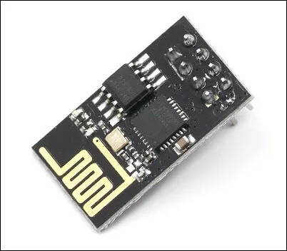
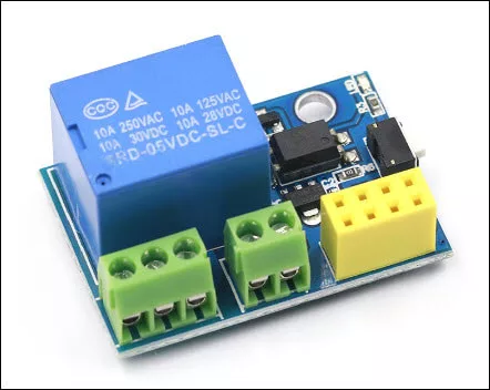
The ESP-01 Wi-Fi module shown in Figure 1 is a widely known member of the ESP8266 microcontroller board family. Because of its low cost and small size, it is usually used for applications where only a few GPIOs (General Purpose Input / Output) are needed. One such application is the ESP-01 Wi-Fi Relay Module shown in Figure 2.
Did you know that there are two (2) versions of ESP-01 Wi-Fi modules? Check out the article:
Difference Between ESP-01 and ESP-01S
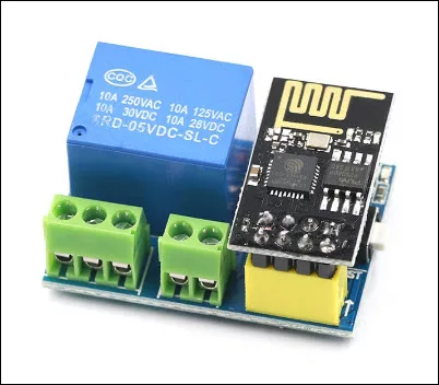
The ESP-01 Wi-Fi relay module is used as a smart switch for remotely turning on and off any device connected to it. A pre-programmed ESP-01 module is inserted into the relay module to serve as a microcontroller for the relay. The attached ESP-01 module also provides the Wi-Fi capability to the relay module to enable a computer or a smartphone to control the relay module remotely or wirelessly.
ESP-01 Module Programmer
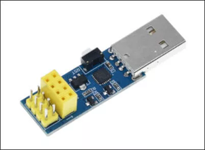
In order to use the ESP-01 Wi-Fi relay module, a programmer is needed to program the ESP-01 module. An example of an ESP-01 programmer is shown in Figure 3. If you do not a have an ESP-01 programmer module, you can make one if you have a USB-to-serial converter. Or simply use an Arduino board as an ESP-01 programmer if you have an available Arduino board. For details on how to make a DIY ESP-01 programmer, see the article: ESP-01 and ESP-01S Pinout and Configuration
Schematic Diagram of ESP-01 Wi-Fi Relay Module
Before we start programming the ESP-01 module to be used on the ESP-01 Wi-Fi relay module, let us first study the schematic diagram of the ESP-01 Wi-Fi relay module. There are two (2) versions of ESP-01 Wi-Fi relay modules. Version 1 is shown in Figure 5 and Version 4 is shown in Figure 6.
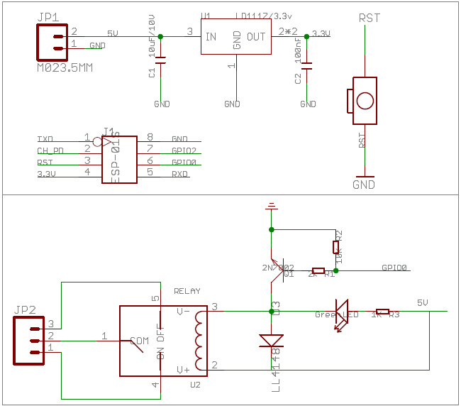
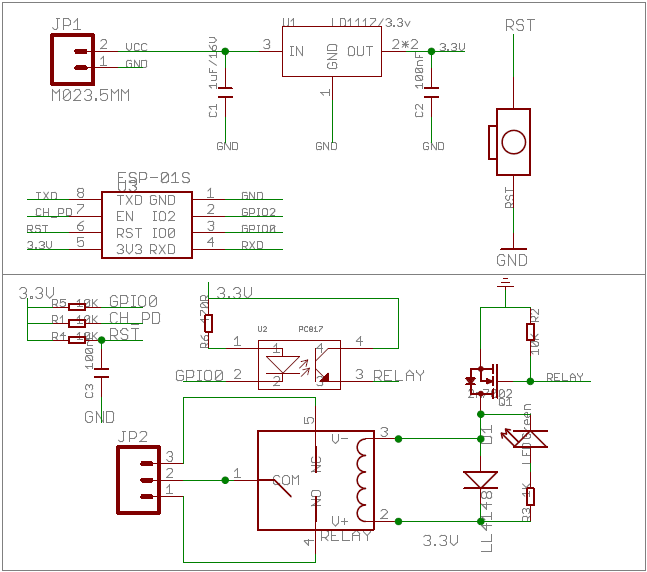
An examination of the two (2) schematic diagrams above will show that the difference in the two versions has something to do with the relay driver. On version 1, the relay is driven by an NPN junction transistor. On the other hand, on version 4, the relay is driven by an N-channel MOSFET transistor. Also, in version 4, the MOSFET driving the relay is in turn being driven by an opto-coupler.
In terms of programming, we should note that on both versions, the relay is activated by the ESP-01 module thru port GPIO0. However, on Version 1, the relay uses ACTIVE HIGH logic levels. That is, a logic HIGH on GPIO0 will activate the relay and a logic LOW will deactivate it. On the other hand, on a Version 4 model, the relay is activated using ACTIVE LOW signals. This means that a logic HIGH will turn OFF the relay and a logic LOW will turn it ON. In short, the two versions use opposite signals for activating the relay. These differing signals should be taken into account when programming the ESP-01 module. Or else, turning ON the relay may result to it being turned OFF instead. And vice versa, turning the relay OFF may cause the relay to turn ON.
How to Program the ESP-01 Module for Use with the Wi-Fi Relay Module
In this article, we will pre-program the ESP-01 module with NodeMCU or Lua program. Afterwards, we will create a smartphone app to control the ESP-01 Wi-Fi relay module remotely. It is also possible to program the ESP-01 module with the Arduino IDE. If you would prefer an Arduino IDE program for the ESP-01 module, please see – How to Control ESP-01 Without a Router.
Flashing the NodeMCU Firmware on ESP-01 Module
First, we need to install the NodeMCU firmware into the ESP-01 module. There are several ways to do this but we will use the one that I think is the easiest. Download the NodeMCU Flasher from Github. Extract the zip file and run the file “ESP8266Flasher.exe”. There are two versions of ESP8266Flasher.exe, a Win32 and a Win64 version. Select the appropriate version for your computer.
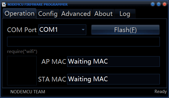
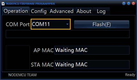
Plug in your ESP-01 programmer with the ESP-01 module to your computer’s USB port. The NodeMCU Flasher should be able to detect the ESP-01 programmer and automatically change the COM Port setting. If this is your first time to use your ESP-01 programmer, you may have to install the device driver for it.
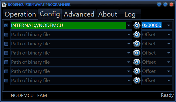
Click on Config tab of the NodeMCU Flasher and verify that you have the settings INTERNAL://NODEMCU and hex 0x00000. The INTERNAL://NODEMCU setting tells the NodeMCU Flasher to use the NodeMCU firmware that comes with the NodeMCU Flasher installation (the firmware file can be found under the Resources/Binaries directory). Meanwhile, the setting 0x00000 is the memory starting location where the NodeMCU firmware will be installed. See Figure 9 for the correct settings.
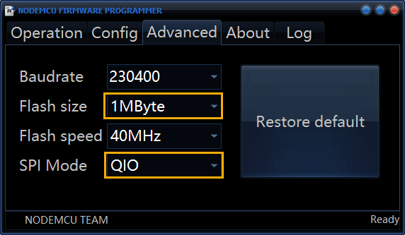
Next, click on the Advanced tab of the NodeMCU Flasher. Change the Flash size to 1Mbyte and the SPI mode to QIO. These two (2) settings are specific to ESP-01 modules, see Figure 10 below.
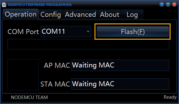
Click back on the Operation tab and click on the Flash(F) button to start flashing the NodeMCU firmware to the ESP-01 module. Please refer to Figure 11.
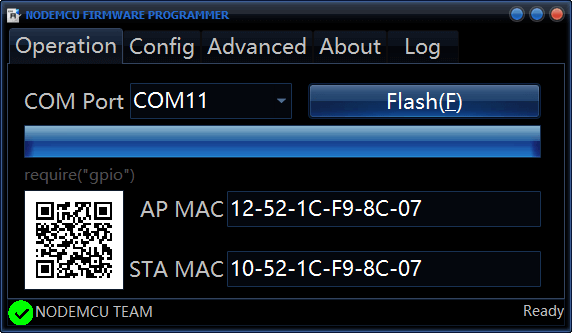
Wait for the progress bar to be filled up and you should see a green checkmark at the bottom left of the NodeMCU Flasher screen as depicted in Figure 12.
We have now successfully installed the NodeMCU firmware on the ESP-01 module, so we will go to the next procedure.
ESPlorer Integrated Development Environment
ESPlorer is an Integrated Development Environment (IDE) used for programming ESP8266 modules like ESP-01 with NodeMCU and Micropython. Download the ESPlorer from Github. Extract the zip file and run the file “ESPlorer.bat”.
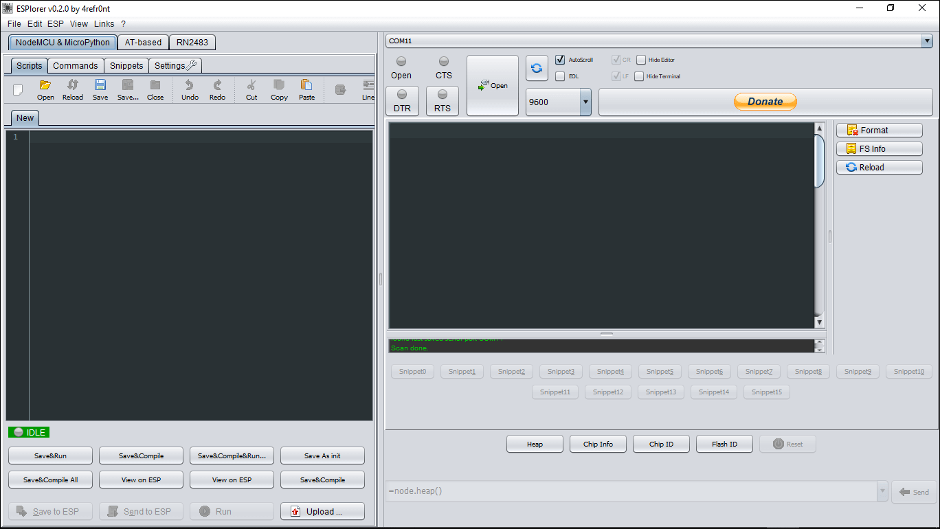
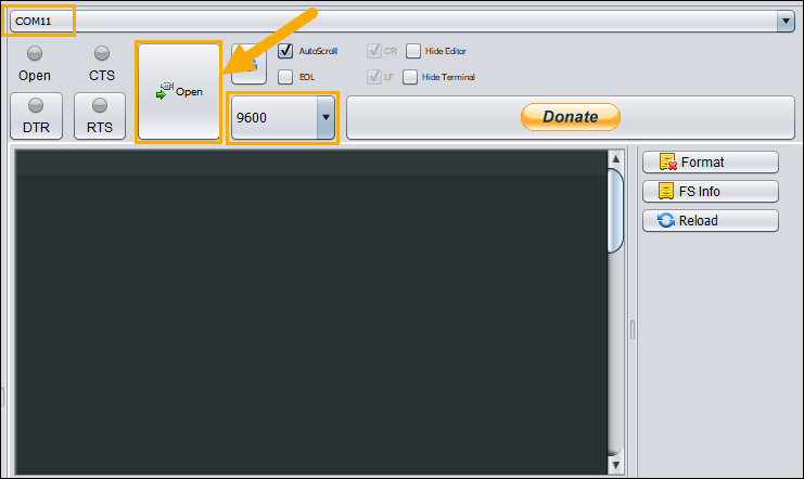
Make sure that the proper COM port for your ESP-01 programmer is selected and the baud rate setting is 9600 baud (see Figure 14). Then click on the Open button.
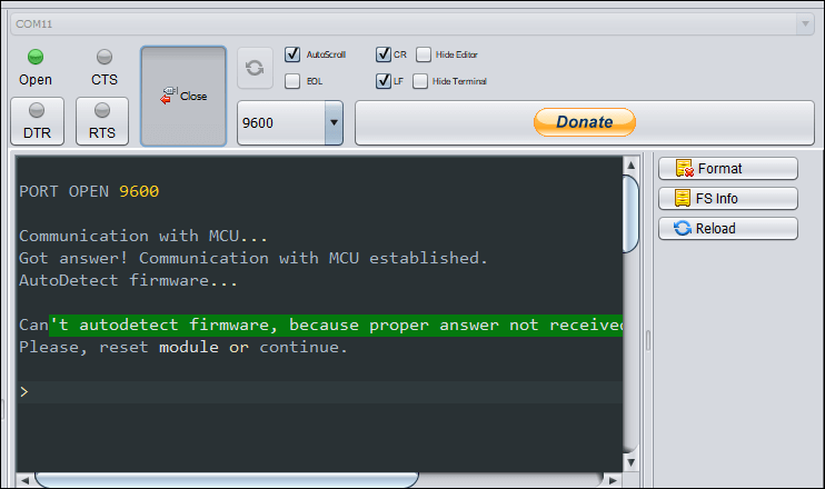
If the ESPlorer can’t autodetect the NodeMCU firmware, reset the ESP-01 module by pressing the reset button on your ESP-01 programmer. Or click on the RTS button on the ESPlorer IDE twice. When you click the RTS button on the ESPlorer IDE, it sends a RESET signal to the connected ESP-01 programmer module.
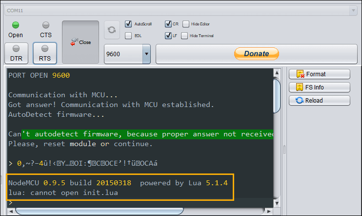
After resetting the ESP-01 module, you should see a message with the NodeMCU firmware version. This verifies that you have successfully flashed the ESP-01 module with the NodeMCU firmware in the preceding procedure.
If the ESPlorer IDE cannot detect your NodeMCU firmware, see the article:
ESPlorer Can’t Autodetect Firmware
The Lua Program
Copy and paste the following Lua program on the left pane of the ESPlorer IDE.
print("Ready to start soft ap")

local str=wifi.ap.getmac();
local ssidTemp=string.format("%s%s%s",string.sub(str,10,11),string.sub(str,13,14),string.sub(str,16,17));

cfg={}
cfg.ssid="ESP8266_"..ssidTemp;
cfg.pwd="12345678"
wifi.ap.config(cfg)

cfg={}
cfg.ip="192.168.1.1";
cfg.netmask="255.255.255.0";
cfg.gateway="192.168.1.1";
wifi.ap.setip(cfg);
wifi.setmode(wifi.SOFTAP)

str=nil;
ssidTemp=nil;
collectgarbage();

print("Soft AP started")
print("Heep:(bytes)"..node.heap());
print("MAC:"..wifi.ap.getmac().."\r\nIP:"..wifi.ap.getip());

led1 = 3
led2 = 4
gpio.mode(led1, gpio.OUTPUT)
gpio.mode(led2, gpio.OUTPUT)
srv=net.createServer(net.TCP)
srv:listen(80,function(conn)
    conn:on("receive", function(client,request)
        local buf = "";
        buf = buf.."HTTP/1.1 200 OK\n\n"
        local _, _, method, path, vars = string.find(request, "([A-Z]+) (.+)?(.+) HTTP");
        if(method == nil)then
            _, _, method, path = string.find(request, "([A-Z]+) (.+) HTTP");
        end
        local _GET = {}
        if (vars ~= nil)then
            for k, v in string.gmatch(vars, "(%w+)=(%w+)&*") do
                _GET[k] = v
            end
        end

        if(_GET.pin == "ON1")then
              gpio.write(led1, gpio.HIGH);
			  print("led1 on")
        elseif(_GET.pin == "OFF1")then
              gpio.write(led1, gpio.LOW);
			print("led1 off")
        elseif(_GET.pin == "ON2")then
              gpio.write(led2, gpio.HIGH);
			print("led2 on")
        elseif(_GET.pin == "OFF2")then
              gpio.write(led2, gpio.LOW);
			print("led2 off")
        end
        client:send(buf);
        client:close();
        collectgarbage();
    end)
end)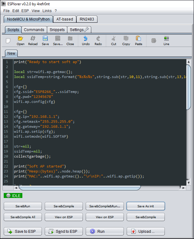
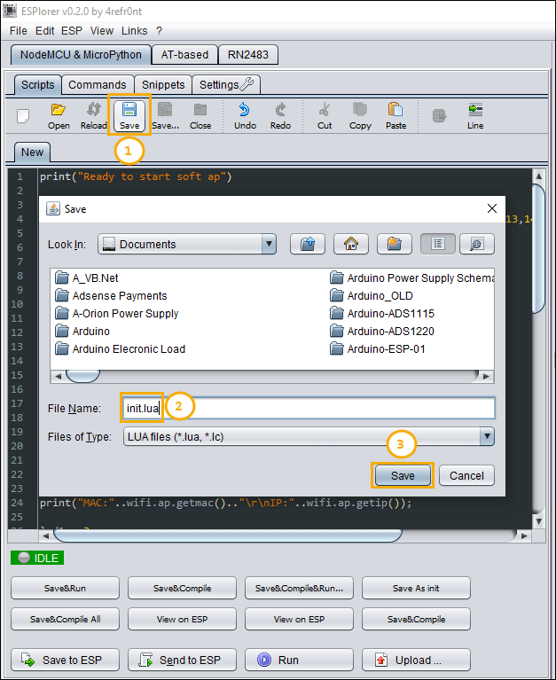
Save the file to your computer. Click the Save button on the top left pane (1). Name the file as “init.lua” (2). Then click on the Save button on the Save screen (3).
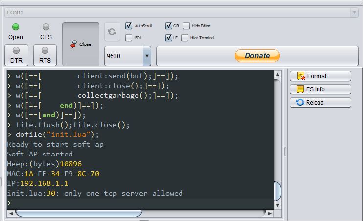
After saving the program to your hard disk, the ESPlorer IDE uploaded the file init.lua to your ESP-01 module and ran the program (dofile(“init.lua”)).
Testing the ESP-01 Module Access Point
Before we proceed to building the smartphone app to control the ESP-01 Wi-Fi relay module, let us first check if we have successfully programmed the ESP-01 module.
Get your smartphone and scan for Wi-Fi devices. With my Android smartphone, I would go to the “Settings/Network and Internet/Wi-Fi” setting. See Figure 20. You should see the Wi-Fi SSID “ESP8266_XXXXXX” where XXXXXX is the last six digits of your ESP-01 module’s MAC address.
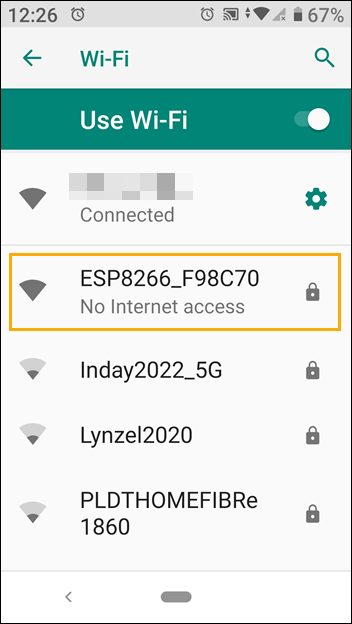
Connect your smartphone to the ESP-01 access point by entering the password “12345678” (Figure 21).
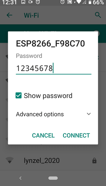
Figure 22 below shows the smartphone connected to the ESP-01 module’s access point.
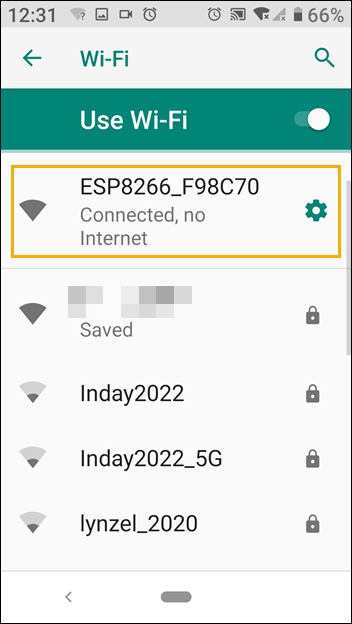
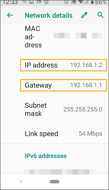
Click on the gear icon to display the network details. Your smartphone will be assigned an IP address of 192.168.1.2. The gateway is the IP address of the ESP-01 access point.
Now we are ready to create the smartphone app to control the ESP-01 Wi-Fi relay module.
How to Create the Smartphone App to Control the ESP-01 Wi-Fi Relay Module
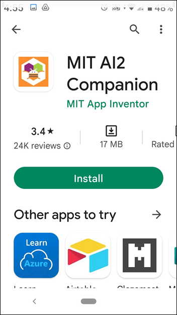
We are going to use the MIT App Inventor 2 to create a smartphone app to control the ESP-01 Wi-Fi relay module. First, we need to download the MIT App Inventor 2 Companion App to our smartphones. We will need it to facilitate installing the created controller app to our smartphones.
Next, download the source code from Github – ESP8266 Controller. Extract the file ESP8266_Controller.aia.
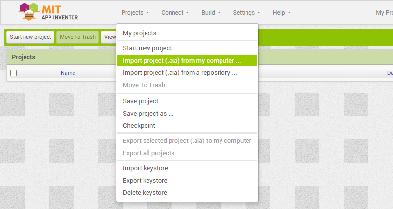
Go to MIT App Inventor website and click on the Create Apps! button.

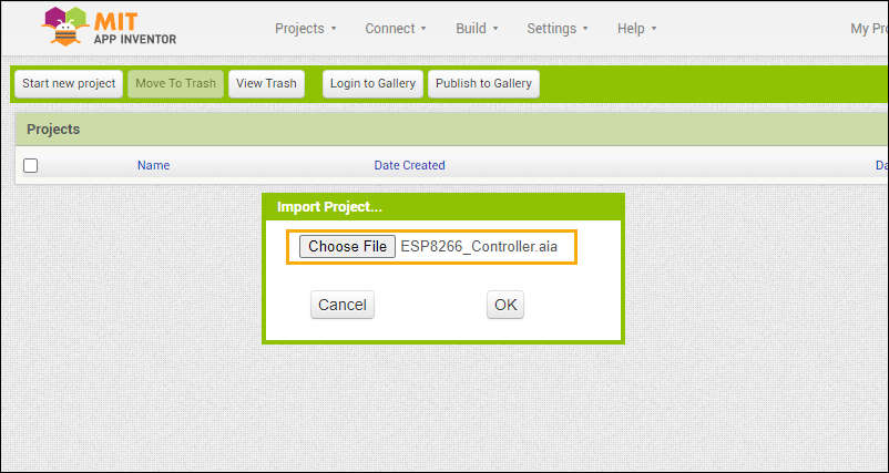
Import the project ESP8266_Controller.aia (the file downloaded from Github).
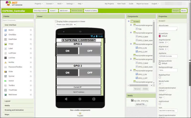
The ESP8266 controller app designers view.
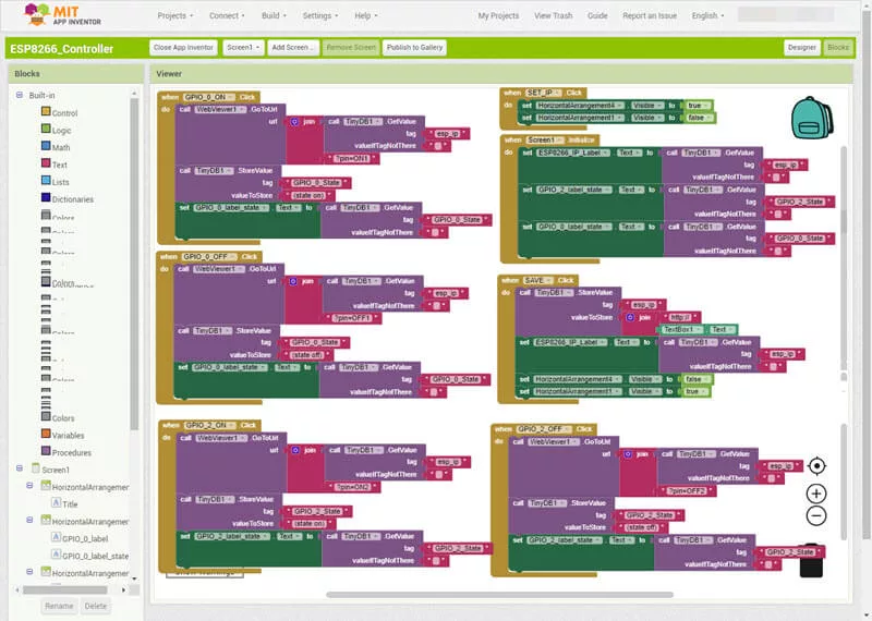
If you want to modify how the program works, go to the Blocks view.
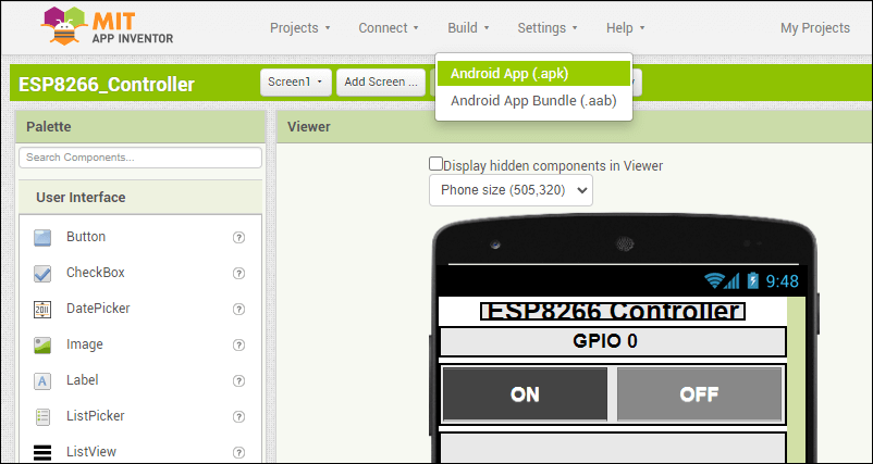
Compile and build the app by clicking the Build/Android App(apk) item on the menu. Refer to Figure 30 below.
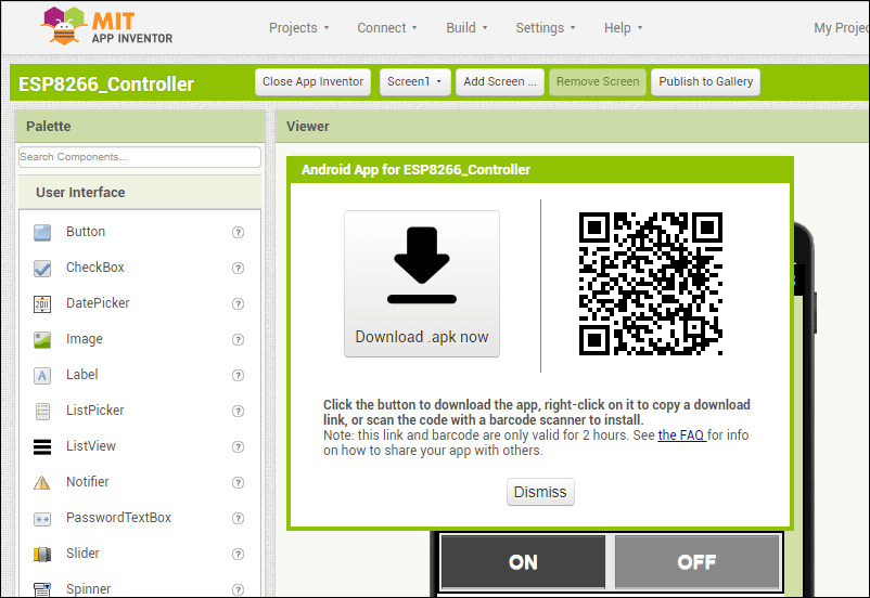
After a successful build, a bar code will appear on your computer’s screen (see Figure 31). Scan the bar code with your smartphone using the MIT App Inventor Companion app. Follow the instructions on your smartphone to install the ESP8266 Controller app.
How to Use the ESP8266 Controller App to Control the ESP-01 Wi-Fi Relay Module
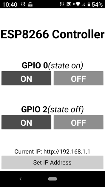
Remove the ESP-01 module from the programmer module and insert it into the ESP-01 Wi-Fi relay module. Provide power to the relay module. Next, connect the smartphone to the ESP-01 access point as discussed above on testing the ESP-01 module access point. Then, open the ESP8266 Controller app and set the IP address to “192.168.1.1”.
You may now enjoy playing around with your new smart switch ESP-01 Wi-Fi relay module using the ESP8266 Controller smartphone app.
Related Articles on How to Use ESP-01 Wi-Fi Relay Module
How to Program ESP-01 with Arduino IDE
How to Set up Arduino IDE for ESP8266 Programming
How to Test an ESP-01 ESP8266 Module
How to Control ESP-01 thru a Router
How to Control ESP-01 Without a Router
ESP-01 with RTC and LCD Display
How to Save and Restore ESP8266 and ESP32 Firmware
NodeMCU V3 ESP8266 Pinout and Configuration
How to Test a NodeMCU V3 ESP8266 Dev Board
How to Use AT-09 BLE with Arduino and Smartphone
References on How to Use ESP-01 Wi-Fi Relay Module
ESP8266 on Wikipedia
ESP-01 Wi-Fi Relay Module on Shopee