Arduino does not have a built-in Digital to Analog Converter (DAC). However, in some situations, like controlling motors and LEDs, we can use Arduino’s PWM outputs. That is, by varying the duty cycle of a PWM output on a digital pin, we can obtain a variable analog voltage from 0 volt to 5 volts. But if we need a more precise analog output voltage, we can instead use an MCP4725 DAC module or breakout board for Arduino.
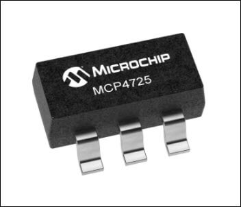
Microchip MCP4725 Integrated Circuit
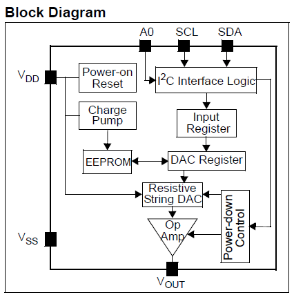
The MCP4725 is a 12-bit Digital to Analog Converter with EEPROM memory. It uses the I2C protocol to communicate with an MCU. List of notable features:
- 12-bit resolution
- I2C protocol interface
- On board EEPROM memory
- 0.2 LSB Differential Nonlinearity (DNL)
- External address pin
- Power down mode
- Fast settling time
- Low power consumption
- Rail-to-rail output
- Single supply operation
- External voltage reference
- Eight available addresses
- Standard, fast, and high-speed modes
- Small SOT-23 package
- Extended temperature range
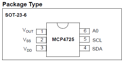
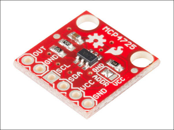
The MCP4725 chip uses a small 6-pin SOT-23-6 package. That is to say, it is an SMD (Surface Mount Device) device. Also, the chip is really very small, with its plastic body measuring around 2 x 3 mm.
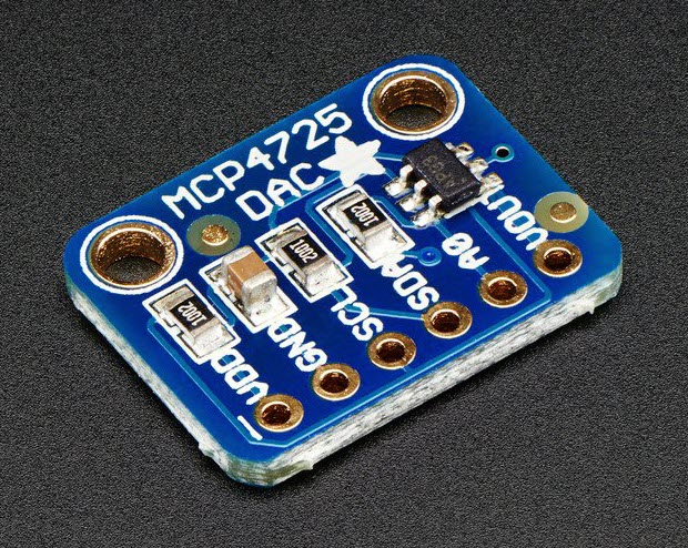
The MCP4725 Modules or Breakout Boards for Arduino
Since the MCP4725 chip comes in a very small package, it is hard to solder it on a PCB. Luckily, both SparkFun and Adafruit have a breakout board or an MCP4725 module. Moreover, MCP4725 modules from Chinese cloners are everywhere. As a matter of fact, almost every popular online shopping stores have them on their inventory. As a result, I have seen modules selling at very cheap prices. Some are selling at almost a dollar a piece (Adafruit: $4.95, SparkFun: $5.25).
MCP4725 DAC Module Schematic Diagram
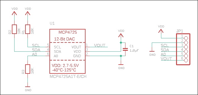
Shown above is the MCP4725 DAC Module for Arduino. The schematic diagram is a screenshot taken from the Adafruit documentation. It is representative of most of the MCP4725 breakout modules.
Let us take a look at the different parts of the schematic. First, two 10K resistors are connected on pins 4 and 5, the SDA and SCL pins respectively. The resistors pull the pins to the VDD potential (they are called pull-up resistors). The I2C interface needs them for proper operation. Second, another 10K resistor connects to the A0 pin. This resistor selects the I2C address to be used by the module. Third, a 1.0 microfarad capacitor connects the VDD and GND pins. This is a power supply de-coupling capacitor. It is there for reducing the noise coming from the power supply. And lastly, the terminal JP1 breaks out all the MCP4725 pins for external connections.
Supply Voltage (VDD or VSS)
This pin requires an appropriate bypass capacitor of
Page 13, Datasheet Entitled: 12-Bit Digital-to-Analog Converter with EEPROM Memory
about 0.1 μF (ceramic) to ground. An additional 10 μF
capacitor (tantalum) in parallel is also recommended to
further attenuate high frequency noise present in
application boards. The supply voltage (VDD) must be
maintained in the 2.7V to 5.5V range for specified
operation.
in SOT-23-6
MCP4725 Module and Arduino Wiring Diagram
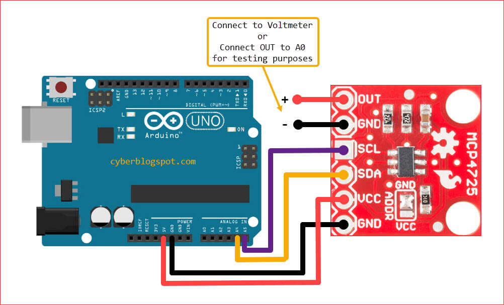
The wiring diagram above shows how easy it is to connect the MCP4725 module to Arduino. First, connect the VCC of the module to the 5V pin of the Arduino board. If you want, you may also power the module using the 3V3 (3.3V) pin. In this case, the module will use the 3.3V as the voltage reference for its measurement instead of 5 volts. Then, connect the GND terminal of MCP4725 to the corresponding GND terminal of the Arduino board.
Second, connect the SDA and the SCL pins of the MCP4725 module to Arduino’s D4 and D5 respectively. This is because, D4 is Arduino’s SDA pin and D5 is its SCL pin.
Finally, if you want to monitor the DAC output voltage using a voltmeter, connect the OUT terminal to the positive terminal of a voltmeter and the GND terminal to the negative terminal of the voltmeter. But if you want to simply use the Arduino to measure the output voltage from the DAC, then connect the OUT terminal to the A0 terminal on the Arduino board. Or, you may use any of the other free analog inputs (A1, A2, or A3).
Arduino Library for MCP4725 DAC Module
How to Install the MCP4725 Library
Before we can use the MCP4725 module, we need to install the library files for Arduino. To install the library files, use the Library Manager that is available on the Tools -> Manage Libraries. You can find this on the main menu of the Arduino IDE.
Adafruit Library Versus Rob Tillaart Library
Arduino IDE comes with two libraries for the MCP4725 module. One is from Adafruit and the other one is from Rob Tillaart. The Adafruit library version has a very small set off procedures. As a matter of fact, the Adafruit library has only a class constructor, an initialization, and a write procedure. No more, no less. Below is an excerpt from the Adafruit MCP4725 library header file. It shows the three (3) procedures. First is the Adafruit_MCP4725(). Second, the begin() procedure. And lastly, the setVoltage() procedure.
class Adafruit_MCP4725 {
public:
  Adafruit_MCP4725();
  bool begin(uint8_t i2c_address = MCP4725_I2CADDR_DEFAULT,
             TwoWire *wire = &Wire);
  bool setVoltage(uint16_t output, bool writeEEPROM,
                  uint32_t dac_frequency = 400000);
}
The other MCP4725 library, the one from Rob Tillaart has many additional useful procedures. Shown below is the excerpt from the header file showing the different methods available.
class MCP4725
{
public:
  explicit MCP4725(const uint8_t deviceAddress, TwoWire *wire = &Wire);

#if defined(ESP8266) || defined(ESP32)
  bool     begin(const uint8_t dataPin, const uint8_t clockPin);
#endif
  bool     begin();
  bool     isConnected();

  // uses writeFastMode
  int      setValue(const uint16_t value = 0);
  // returns last value set - cached - much faster than readDAC();
  uint16_t getValue();

  // 0..100.0% - no input check.
  int      setPercentage(float perc = 0) { return setValue(round(perc * (0.01 *
MCP4725_MAXVALUE))); };
  float    getPercentage() { return getValue() * (100.0 / MCP4725_MAXVALUE); };

  int      writeDAC(const uint16_t value, const bool EEPROM = false);
  // RDY isdepreciated in the future, use ready() instead.
  // inline bool RDY()  { return ready(); };
  bool     ready();
  uint32_t getLastWriteEEPROM()  { return _lastWriteEEPROM; };
  uint16_t readDAC();
  uint16_t readEEPROM();

  // experimental
  int      writePowerDownMode(const uint8_t PDM, const bool EEPROM = false);
  uint8_t  readPowerDownModeEEPROM();
  uint8_t  readPowerDownModeDAC();
  int      powerOnReset();
  int      powerOnWakeUp();
}
Sample Sketch for Using MCP4725 Module
For simplicity, we will use the Adafruit library for the MCP4725. To use the library, first, we need to reference the library files in our sketch.
#include <Adafruit_MCP4725.h>
Then create an object or an instance of the Adafruit_MCP4725 class. You may use any name you want for the object name. In this case, I am using “myDAC”.
Adafruit_MCP4725 myDAC;
Afterwards, in the loop() procedure, we initialize the DAC object. Here, the begin() method needs the address of the MCP4725 module in hex format. The address is hardwired on the module. But, depending the module you have, it’s either 0x60, 0x61, or 0x62.
void setup(){
myDAC.begin(0x60);
}
Finally, in the loop() procedure, we use the method setVoltage() to make the MCP4725 output a certain voltage.
void loop(){
myDAC.setVoltage(2048, false);
}
How the setVoltage() Method Works
As shown in the header file excerpt above, the setVoltage() method is defined as follows:
bool setVoltage(uint16_t output, bool writeEEPROM,
                  uint32_t dac_frequency = 400000);
The setVoltage() method has three (3) parameters, the first two (2) of which are required. The three (3) parameters are output, writeEEPROM, and dac_frequency.
The first parameter, output, accepts a value ranging from 0 to 4095. This is a 12-bit value that represents the digital input code to the DAC. The maximum value of 4095 is the result of the DAC having a 12-bit resolution. That is, 212-1 = 4095. In other words, the DAC can generate 4095 different output voltages.
The second parameter, writeEEPROM, is either “true” or “false”. Because the MCP4725 allows us to store the DAC input value into its built-in memory, the second parameter allows us to enable or disable this feature. The main use of this feature is for restoring the previous state of the DAC after a reset or power-down mode.
MCP4725 DAC Frequency
The third parameter is the dac_frequency. The DAC frequency refers to the I2C data transfer rate. In this case, it is the data transfer rate between the Arduino board and the MCP4725 module. This is an optional parameter. Unlike the first two (2) parameters, output and writeEEPROM, you are not required to provide any value for the dac_frequency. In that case, it will use the default value of 400,000. The MCP4725 DAC has three speed modes, the standard mode (100khz), the fast mode (400khz), and the high speed mode (3.4Mhz). Therefore, the valid arguments for the dac_frequency are 100,000, 400,000 (default), and 3,400,000.
FYI: The default Arduino I2C protocol speed is 100khz.
To sum up on the setVoltage() method, the procedure accepts three arguments which are the output (0 to 4095), the writeEEPROM (true or false), and the optional dac_frequency (1khz, 4khz, or 3.4Mhz).
//Examples
myDAC.setVoltage(2048, false); //output a voltage about 1/2 of Vref
myDAC.setVoltage(4095, true);  //output the maximum voltage and store on EEPROM
myDAC.setVoltage(0, false, 4300000)  //set to minimum voltage, don't store, use //high speed mode
How to Output a Specific Voltage using setVoltage()
As discussed above, setVoltage() accepts a value in the range of 0 to 4095. We know that 0 means we should get a 0 volts output voltage. Also, 4095 means that we should get a 5 volts output voltage. This is of course assuming that we are using a 5V power supply. Again, our voltage reference here is 5V (equal to the supply voltage).
What value should we use for the setVoltage() if we want an output voltage of 1V? 2V? 2.75V? etc.?
As it turns out, we need to compute the value of the input code. The way the DAC works, it divides the Vref voltage into 4095 discrete values. That is, Vref / 4095 or in this case 5V / 4095. This gives us 0.00122 or about 1.2mV. So, the digital code 1 is 1.2mv, digital code 2 is 2.4mV, digital code 3 is 3.6mV, and so on.
The MCP4725 Datasheet Formula
The MCP4725 datasheet, on page 19, gives us the formula for computing the output voltage.
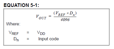
Based on the formula above, let’s compute Dn or the digital input code for a specific output voltage Vout.
Cross multiplying, we get
and after transposition, we get
We seem to have a problem here. The datasheet used 4096 for the resolution and not 4095. As a result, we will surely get a wrong value. Let’s say we want an output voltage of 5V. Using the values Vout=5V and Vref=5V, we get
But setVoltage() only accepts a value from 0-4095. Using a value of 4096 will surely fold over to 0.
The Dividend Debate
In Arduino, several schools of thought exist on how to compute the voltage from the value given by analogRead(). Some say the formula is Vout = (Vref * Dn) / 1024. Others say it is Vout = (Vref * Dn) / 1023. And still, there are those who go in-between, Vout = (Vref * (Dn + 0.5)) / 1024.
A good treatment of this issue can be found on https://www.gammon.com.au/forum/?id=12779
In order to match the setVoltage() parameter, I will stick with the following formula:
Let’s test the formula,
Vout = 0V, Vref = 5V, we get Dn = 0
Vout = 5V, Vref = 5V, we get Dn = 4095
Now, if we want an output voltage of 1V, we have Dn = (1V * 4095) / 5V = 819. Therefore, to set the output voltage of the MCP4725 module to 1V, we should use setVoltage(819, false);
Issues with Using MCP4725 DAC Module
- MCP4725 does not have a separate pin for external voltage reference. MCP4725 uses the applied VCC as its voltage reference. Hence, it needs a clean and well regulated power supply.
- Although an external voltage reference can be used thru the VCC pin, VCC is limited to 2.7V minimum. As a result, it is not possible to use the standard 1.028V, 2.048V and 2.500V voltage references.
- Problem with the offset voltage error. At 0 digital input code where 0 volts is expected, I get a 6.8 millivolts output. That is, an almost 7mV of offset error. Also, I have seen a post on a forum site where someone was asking how to remove a 32mV offset error. The offset error specification for MCP4725 is 0.75% of FSR. In other words, if you are using a 5-volt VCC, the offset error can be up to 37.5mV( 5V multiplied by .0075). Although the offset error is easy to calibrate in software by simply subtracting the offset, the lower range up to the offset error voltage becomes unusable. A hardware solution is possible (summing amplifier) to remove the offset but may need a precision op amp, or additional error may be introduced.
References on How to Use MCP4725 Module with Arduino
MCP4725 Datasheet
ADC conversion on the Arduino (analogRead)
Related Articles on How to Use MCP4725 Module with Arduino
1 – How to Use ADS1220 ADC Module with Arduino
2 – How to Program ESP-01 with Arduino IDE
3 – How to Install Esptool on Windows 10
4 – How to Save and Restore ESP8266 and ESP32 Firmware
5 – How to Test a NodeMCU V3 ESP8266 Dev Board
6 – How to Test NodeMCU V3 Using Esptool
7 – NodeMCU V3 ESP8266 Pinout and Configuration
8 – NodeMCU ESP-32S Pin Configuration
9 – ESP-01 ESP8266 NTP Clock with LCD Display
10 – ESP-01 with RTC and LCD Display
11 – How to Control ESP-01 thru a Router
12 – How to Control ESP-01 Without a Router