The MCP4921 is a Digital to Analog Converter IC from Microchip. You can use the MCP4921 DAC on Arduino projects that require a precise DAC. The MCP4921 chip has a single-channel 12-bit digital to analog converter. However, if you need more than one (1) channel, a two (2) channel version, the MCP4922 is also available.
Features of MCP4921 DAC Chip
- 12-bit single-channel DAC
- Rail-to-rail output voltage
- SPI interface speed up to 20 MHz
- LDAC pin for synchronizing DAC output
- Fast settling time
- Selectable gain output
- External voltage reference pin
- External multiplier mode – see application note
- Single-supply operation
- Extended temperature range
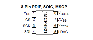
Pin Configuration of MCP4921
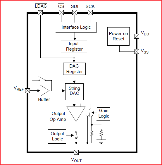
The MCP4921 Functional Block Diagram
Arduino Board and MCP4921 Wiring Diagram
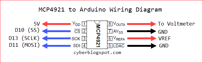
To connect the MCP4291 DAC to an Arduino development board, use the wiring diagram shown above.
Take note of the following: First, the VDD (pin1) which is the power supply input, accepts either a 3.3V or a 5V supply voltage. Second, you can connect the CS pin (pin 2) to any available digital output pin, D2 thru D9. Third, the Vrefa pin (pin 6) can use a voltage reference or can be connected directly to the VDD supply. Fourth, the LDAC pin (pin 5) is tied together with the AVSS pin (pin 7) to the Arduino ground (GND). Finally, you can connect the output pin Vouta (pin 8) to a voltmeter. Otherwise, you can use one of Arduino’s analog pins (A0 thru A5 on Arduino Uno) for measurement purposes.
The MCP4921 Arduino Library
The MCP_DAC Library by Rob Tillaart covers two (2) lines of 8, 10, and 12-bit DACs along with their single and dual-channel versions. Specifically, these are the MCP48XX series and the MCP49XX series. The MCP48XX series differs from the MCP49XX with its built-in voltage reference. That is, the MCP48XX series comes with a built-in 2.048V voltage regulator while the MCP49XX series needs to be provided with an external voltage regulator.
The MCP48XX series is designated as follows:
MCP4801 – 8-bit single-channel
MCP4802 – 8-bit dual-channel
MCP4811 – 10-bit single-channel
MCP4812 – 10-bit dual-channel
MCP4821 – 12-bit single-channel
MCP4822 – 12-bit dual-channel
The MCP49XX series follows the same designations.
MCP4901 – 8-bit single-channel
MCP4902 – 8-bit dual-channel
MCP4911 – 10-bit single-channel
MCP4912 – 10-bit dual-channel
MCP4921 – 12-bit single-channel
MCP4922 – 12-bit dual-channel
How to Use the Library
Step 1
First of all, we need to include the library’s file header in our sketch.
#include "MCP_DAC.h"
Step 2
Then, create an MCP_DAC object.
MCP4921 myDAC;
This little and simple code needs a lot of explanation. First, although the library is designed for multiple DAC chips as noted above, the object creation is very simple. You simply type the DAC chip’s name and provide your own object name. For example, if you are using an MCP4801 chip, you will simply say:
MCP4801 yourDAC;
Software SPI
Second, the library supports software SPI. The object creation above assumes that we are using hardware SPI. That is, we are using the Arduino’s designated SPI pins. In other words, Arduino’s pin D11 (MOSI) must be connected to the MCP4921’s SDI pin (pin 4). Also, Arduino’s pin D13 (SCLK) must be connected to the MCP4921’s SCK pin (pin 3). Please see Arduino-MCP4921 wiring diagram above. Otherwise, software SPI will be used. In this case, because we are not using the default SPI pin connections, we need to provide the dataout (MOSI) and the clock (SCLK) pins that we are currently using. Assuming we are using D9 pin for MOSI and D8 pin for SCLK, we create the MCP_DAC object in this manner:
MCP4921 yourDAC(9,8);
To sum up on the MCP_DAC object creation, there are two ways to create the object. If we are using the default SPI pins, we simply say MCP4921 yourDAC();. Otherwise, we write MCP4921 yourDAC(9,8), specifying the dataout and clock pins.
Default Settings
Some more things on the MCP_DAC object creation before we proceed. The library creates the DAC object with the following default configuration:
- Gain is 1 (1 or 2)
- Buffered Mode is false (true or false)
- Active Mode (true or false)
- Channel selected is 1 (1 or 2 for dual-channel devices only)
Gain
The maximum output voltage of the MCP4921 DAC depends on the external voltage reference. That is, if we are using a 2.048V voltage reference, then the maximum output voltage is 2.048 volts. But if we need a higher output voltage, then we must change the voltage reference to a higher value. This is where the programmable gain comes in. Instead of changing the external voltage reference, we could simply change the gain to 2X to double the range of the output voltage.
Buffered Mode
The buffered mode refers to the voltage reference input. Using the buffered mode increases the input impedance of pin 6 (Vref). As a result, it reduces the loading effect on the external voltage reference.
Active Mode
The MCP4921 has a power saving mode called shutdown mode. Being in active mode means the DAC is not in shutdown mode.
Selected Channel
This configuration is only for dual-channel devices. This does not apply to the MCP4921 since it has only one channel, which is always the selected channel.
Step 3
Now, let’s go to next step. In the setup() procedure we initialize our newly created MCP_DAC object.
void setup(){
myDAC.begin(10);
}
As previously noted above, the CS (chip select) pin 2 of MCP4921 can be connected to any available digital pin on the Arduino. Whether you used the default Arduino pin 10 or not, you need to provide the CS pin number in calling the begin() procedure.
Step 4
Finally, on the loop() procedure, we use the analogWrite() method to output a specific voltage value.
void loop(){
myDAC.analogWrite(2048);
}
The analogWrite() method accepts a number ranging from 0 to 4095. Assuming that we have an ideal DAC, analogWrite(0) should give us an output voltage of 0 volts. Also, analogWrite(4095) should give us the maximum output voltage equal to Vref. However, with my own testing, the analogWrite(0) gives me around 6mV of output. This is due to the device’s offset error. On the other hand, the analogWrite(4095) produces a voltage lower than Vref because of the DAC’s gain error.
The Complete MCP4921 Library Example
#include "MCP_DAC.h" //reference the library files
MCP4921 myDAC;       //create DAC object

void setup(){
myDAC.begin(10);     //initialize
}

void loop(){
myDAC.analogWrite(2048);  //output a voltage about 1/2 of Vref
}
Programming the MCP4921 Directly with SPI Library
Rob Tillaart, the author of the MCP_DAC library discussed above, included a sample program named MCP4921_standalone.ino. It shows how to program the MCP4921 without even using the MCP_DAC library. I modified the file to highlight the simplicity of the programming required.
#include "SPI.h"
#define MCP4921_CS_PIN 10
void setup()
{
pinMode(MCP4921_CS_PIN, OUTPUT);
digitalWrite(MCP4921_CS_PIN, HIGH);
SPI.begin();
}
void loop(){
setVoltage(2048); //output a voltage 1/2 of Vref
}
void setVoltage(uint16_t value)
{
uint16_t data = 0x3000 | value;
digitalWrite(MCP4921_CS_PIN, LOW);
SPI.beginTransaction(SPISettings(16000000, MSBFIRST, SPI_MODE0));
SPI.transfer((uint8_t)(data >> 8));
SPI.transfer((uint8_t)(data & 0xFF));
SPI.endTransaction();
digitalWrite(MCP4921_CS_PIN, HIGH);
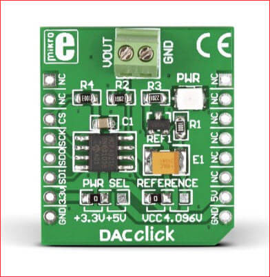
}The MCP4921 DAC click from MikroElektronika
Since the MCP4921 integrated circuit is available on an 8-pin DIP package, there is no need for a module or a breakout board. Although, if you want, there is also a breakout board available. An example of an MCP4921 DAC module is shown below. This DAC module is made by Mikroe.
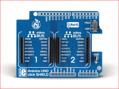
For easy integration with an Arduino Uno board, you can use a Click shield. Below is a picture of a Mikroe Click shield. When plugged into an Arduino Uno board, it will accept two (2) Mikroe Click boards.
Schematic Diagram of MCP4921 DAC Module for Arduino
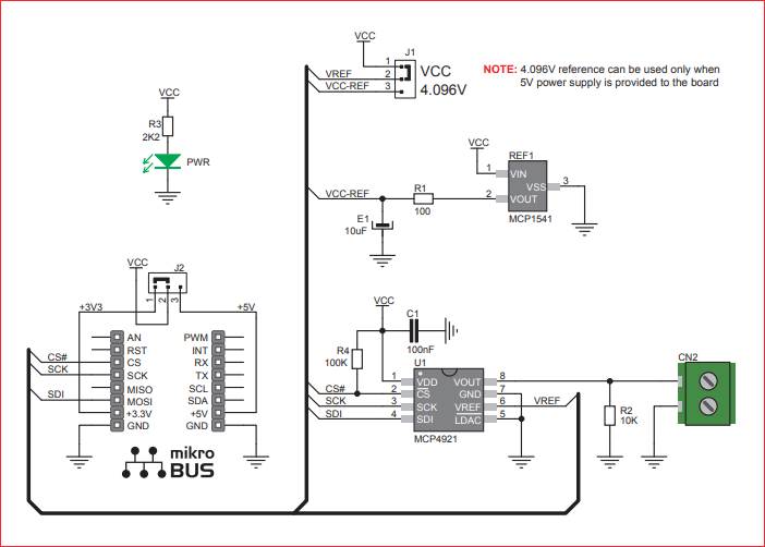
Above is the schematic diagram of the Mikroe MCP4921 DAC module. The good thing with this module is that it has an on-board voltage reference. The on-board voltage reference chip (MCP1541) is a 4.096V reference. It has an initial accuracy of 1% (plus or minus) and has a temperature drift of 50 ppm/degC (plus or minus). Also, since the MCP4921 DAC can be powered from a 3.3V supply, there is a jumper that allows us to select whether to use the 4.096V reference or the Vcc.
Related Articles on How to Use MCP4921 DAC with Arduino
1 – How to Program ESP-01 with Arduino IDE
2 – How to Install Esptool on Windows 10
3 – How to Save and Restore ESP8266 and ESP32 Firmware
4 – How to Test NodeMCU V3 Using Esptool
5 – How to Test a NodeMCU V3 ESP8266 Dev Board
6 – NodeMCU V3 ESP8266 Pinout and Configuration
7 – NodeMCU ESP-32S Pin Configuration
8 – ESP-01 with RTC and LCD Display
9 – How to Use MCP4725 Module with Arduino
10 – How to Use ADS1220 ADC Module with Arduino
References on How to Use MCP4921 DAC with Arduino
MCP4921 Datasheet
MCP_DAC MCP4921 Arduino Library by Rob Tillaart
Hey quick question if you dont mind,
Can i put a voltage of 3.3V on VDD and 5V on the VREFF input to get a 0 to 10 V output? or would this cause problems because the VDD and VREFF are not the same voltages?
Greetings,
Jurjen