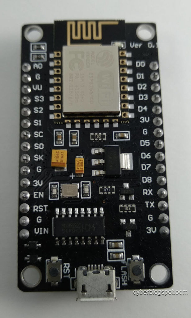
There are many models of microcontroller development boards based on Espressif ESP8266 chip. Unfortunately, different boards have different pin layouts or configurations. This NodeMCU V3 ESP8266 Pinout guide is for the ESP8266-based devkit pictured below.
This particular board was purchased this January 2020 from a local supplier, makerlab-electronics.com.
NodeMCU V3 Development Board Specification
Based on the supplier’s website, the board’s specification is as follows:
- Communication interface voltage: 3.3V.
- Antenna type: Built-in PCB antenna is available.
- Wireless 802.11 b/g/n standard
- WiFi at 2.4GHz, support WPA / WPA2 security mode
- Support STA/AP/STA + AP three operating modes
- Built-in TCP/IP protocol stack to support multiple TCP Client connections (5 MAX)
- D0 ~ D8, SD1 ~ SD3: used as GPIO, PWM, IIC, etc., port driver capability 15mA
- AD0: 1 channel ADC
- Power input: 4.5V ~ 9V (10VMAX), USB-powered
- Current: continuous transmission: ≈70mA (200mA MAX), Standby: <200uA
- Transfer rate: 110-460800bps
- Support UART / GPIO data communication interface
- Remote firmware upgrade (OTA)
- Flash size: 4MByte
As an additional information, this board uses the UART chip CH340G. Remember that other ESP8266 boards use another UART chip, namely Silicon Labs CP2102.
Note the advertised GPIO:
D0 ~ D8, SD1 ~ SD3: used as GPIO, PWM, IIC, etc., port driver capability 15mA
Some websites even advertise the whole set of ESP8266 chip GPIO:
Digital I/O Pins (DIO): 17
Analog Input Pins (ADC): 1
But the fact is, some of the GPIOs are used by the development board for its proper operation. Using them would possibly crash your program. Or may give you unexpected results.
Six of the seventeen GPIOs, marked on the top of the board as S3, S2, S1, SC, S0, and SK, are all used by the board to interface with the 4MB external flash chip. This leaves us with:
Digital I/O Pins (DIO): 11
Analog Input Pins (ADC): 1
Now, if your program is using the hardware serial pins, labeled TX and RX, you are left with only nine (9) usable digital IO and one (1) analog-to-digital IO.
Therefore, in reality, these are the only available GPIOs:
Digital I/O Pins (DIO): 9 - D0 thru D8
Analog Input Pins (ADC): 1 - A0
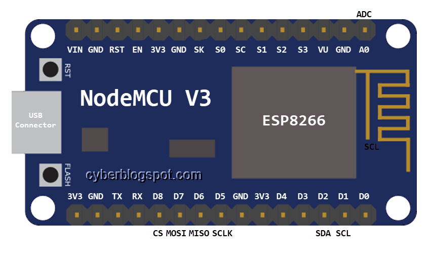
NodeMCU V3 ESP8266 Pinout
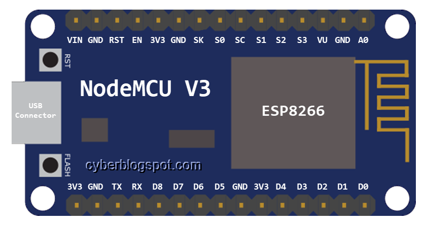
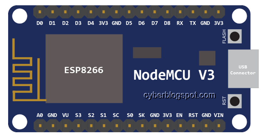
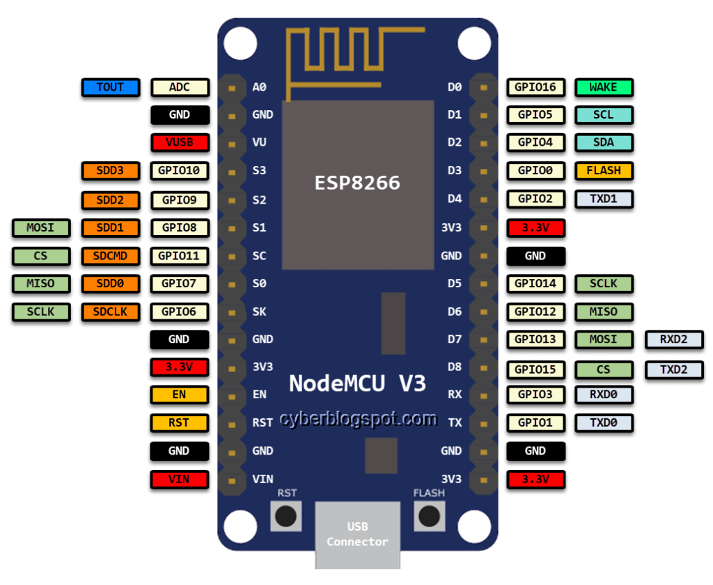
(Board in Upright Position, USB Connector at the Bottom)

ARDUINO IDE PIN REFERENCE
When programming the NodeMCU V3 ESP8266 board with Arduino IDE, we may use the pin labels printed on the top of the board. That is, A0 for the ADC pin and D0 thru D10 for the digital pins (D9 is RX and D10 is TX).
For example, to reference GPIO D0,
#define ledPIN1 D0 // or D1, D2, up to D8
#define ledPIN2 D9 // D9 and RX may be used interchangeably
// or #define LEDPIN2 RX
#define switchPIN D10 // D10 and TX may be used interchangeably
// or #define switchPIN TX

#define inVolts A0

pinMode(ledPIN1, OUTPUT);
pinMode(ledPIN2, OUTPUT);
pinMode(switchPIN, INPUT);  //for demo only, may not be necessary
                          //DIOs are by default INPUT
digitalWrite(ledPIN1, HIGH);
digitalWrite(ledPIN2, LOW);
bool sw = digitalRead(switchPIN);


analogRead(inVolts);  // ADC A0 is for reading only
                      // can't be used as OUTPUT
Summary of Available IO Pins
| Board Label | GPIO | Normal Use | Comments |
| A0 | ADC0 | Input only | Analog input |
| D0 | GPIO16 | Wake up | Pulled LOW, HIGH at boot |
| D1 | GPIO5 | SCL | I2C |
| D2 | GPIO4 | SDA | I2C |
| D3 | GPIO0 | FLASH | Pulled HIGH, do not pull LOW |
| D4 | GPIO2 | BUILT-IN LED | Pulled HIGH, do not pull LOW |
| D5 | GPIO14 | SCLK | SPI |
| D6 | GPIO12 | MISO | SPI |
| D7 | GPIO13 | MOSI | SPI |
| D8 | GPIO15 | CS | SPI, Pulled LOW, do not pull HIGH |
| RX | GPIO3 | RX | May be used as Input, HIGH on boot |
| TX | GPIO1 | TX | May be used as Output, HIGH on boot |
Boot Modes
| D8 GPIO15 | D3 GPIO0 | D4 GPIO2 | BOOT MODE |
| LOW | LOW | HIGH | UART Bootloader |
| LOW | HIGH | HIGH | Boot program in flash |
| HIGH | X | X | SDIO (not used on Arduino) |
Related Articles on NodeMCU V3 ESP8266 Pinout and Configuration
Hardware
NodeMCU ESP32S Pin Configuration
How to Save and Restore ESP8266 and ESP32 Firmware
How to Test NodeMCU V3 Using Esptool
How to Connect a DS3231 to NodeMCU V3
Software
How to Install Arduino IDE on Windows 10
How to Set up Arduino IDE for ESP8266 Programming
How to Install Esptool on Windows 10
Hardware & Software
How to Use MCP4725 Module with Arduino
How to Use ADS1220 ADC Module with Arduino
References on NodeMCU V3 ESP8266 Pinout and Configuration
NodeMCU on Wikipedia – https://en.wikipedia.org/wiki/NodeMCU
ESP8266 on Wikipedia – https://en.wikipedia.org/wiki/ESP8266
IN your code sample, you define Pin2 as RX / D9, then set it as an Output.
BUT in your table you say that RX may be used as an Input, and TX should be Output.
I know 8266 pin usage is confusing, but you seem to be adding to it