
An ADS1115 module or breakout board is a 16-bit analog to digital converter (ADC) that we can use with Arduino. Arduino boards come with a built-in ADC. However, this built-in ADC has a somewhat limited capability. The Arduino ADC, with its 10-bit resolution, pales in comparison with the AD1115’s 16-bit resolution .
To illustrate, let’s assume that we are measuring a 5V voltage. The smallest voltage that Arduino can measure is 5V / 1024 = 0.0049V (or 4.9mV). Comparing with the ADS1115, it can measure a voltage of 5V / 65536 = 0.000076V (or 0.076mV, or 76uV). So, while Arduino’s ADC can sense a voltage change of 4.9mV, the ADS1115 can detect a voltage change as small 76uV.
If you want an even more precise Analog to Digital Converter (24-bit ADC) for Arduino, see How to Use ADS1220 ADC Module with Arduino
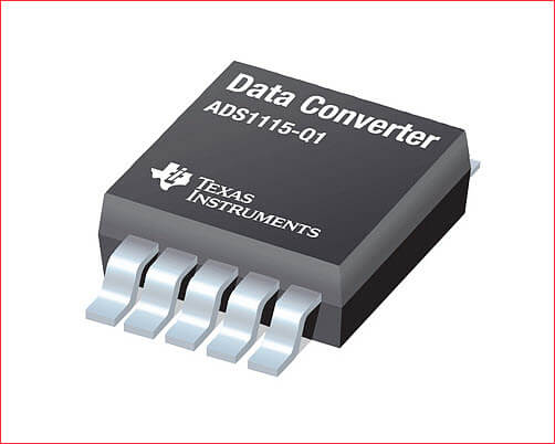
The ADS1115 Chip
The heart of an ADS1115 module is an ADS1115 Integrated Circuit (IC). It is a 4-channel analog to digital converter with 16-bit resolution.
Features of ADS1115
- 16-bit Resolution
- Four (4) Channel Single-Ended or Two (2) Channel Differential Inputs
- I2C Protocol Interface
- Programmable Comparator
- Wide Supply Range
- Low Current Consumption
- Continuous-Conversion Mode
- Programmable Data Rate
- Programmable Comparator
- Single-Cycle Settling
- Internal Low-Drift Voltage Reference
- Internal Oscillator
- Wide Operating Temperature Range
- Available in Ultra-Small X2QFN Package
ADS1115 Pin Configuration
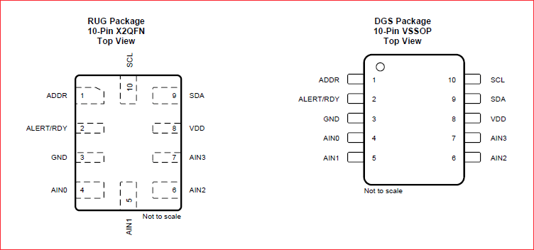
The picture above shows the pinout or the pin configuration of the ADS1115 chip. Let’s go thru the functions of the different pins.
Pins 4, 5, 6, and 7 are the four (4) ADC input pins. We can use these pins as either four (4) single-ended inputs or two (2) differential inputs. Pins 9 and 10 are the terminals for the I2C interface, SDA and SCL respectively. Pin 2 is the Alert/Ready pin which serves as a data ready and alert signal. Pin 1 is the ADDR pin that selects the I2C address for the chip. And finally, pin 8 is the supply positive and pin 3 is the GND terminal.
The ADS1115 Packaging
The ADS1115 chip comes in two packages, the 10-pin X2QFN (Quad Flat No-leads) package and the 10-pin VSSOP (Very Thin Shrink Small Outline Package) package. Both of these packages are really very small. The VSSOP package has a body dimension of around 3mm x 3mm while the X2QFN package is even smaller at a body dimension of 1.5mm x 2mm.
Functional Block Diagram of ADS1115
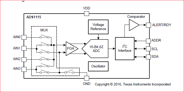
The functional diagram above shows that prior to conversion, a multiplexer selects the input signal. Then, the selected signal feeds into a programmable gain amplifier (PGA). The PGA can programmed to provide amplification of small signals prior to conversion. Subsequently, the input is converted by a 16-bit Delta Sigma converter. The converter uses its own built-in voltage reference and built-in oscillator in measuring the input signal. Finally, the result of the conversion goes into the I2C interface. Also, a comparator provides a signal to the external interface that the result is ready for fetching.
Typical Connection for ADS1115 Chip
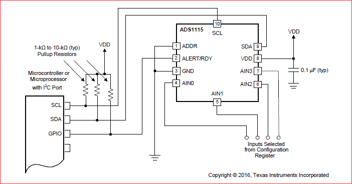
The screenshot above shows how to connect the ADS111 ADC chip to a microcontroller. There are two (2) things to note here. First is the pull-up resistors on the I2C and the GPIO pins. Second is the 0.1 uF (100nF) decoupling capacitor on the VDD pin terminal.
ADS1115 Modules or Breakout Boards for Arduino
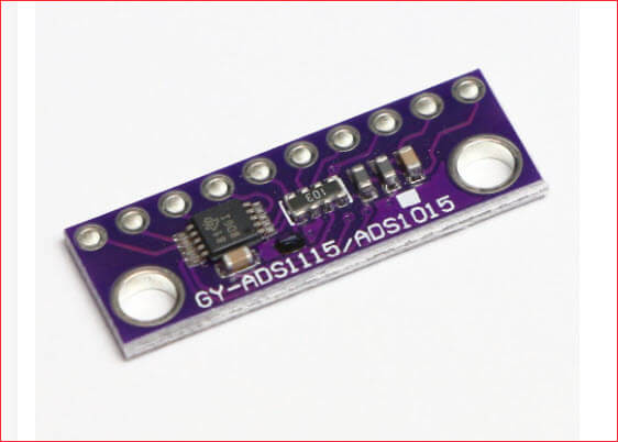
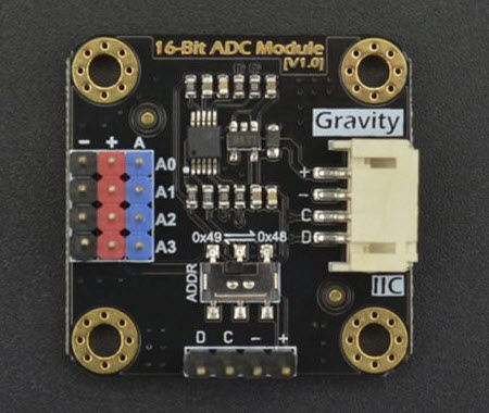
When it comes to breadboarding and prototyping, the very small footprints of the ADS1115 chip is a challenge. Since the ADS1115 chips come in very small packages, it is better to use a ready-made ADS1115 module or breakout board. These modules are widely available and are very inexpensive. Some of the available models are shown below.
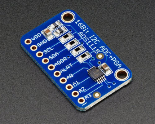
Schematic Diagram of ADS1115 Module
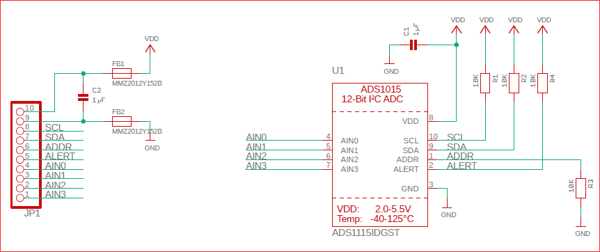
The schematic diagram shown above is the Adafruit’s version of ADS1115 module or breakout board. It follows the typical connection for the ADS1115 chip which was described previously. That is, 10K ohms pull-up resistors are installed on the I2C and Alert pins. Also, there is a 1uF capacitor installed between the VDD pin and the GND which serves as a decoupling capacitor.
How to Connect ADS1115 Module to Arduino
| ADS1115 | Arduino Uno |
|---|---|
| VDD | 5V |
| GND | GND |
| SCL | D5 (SCL) |
| SDA | D4 (SDA) |

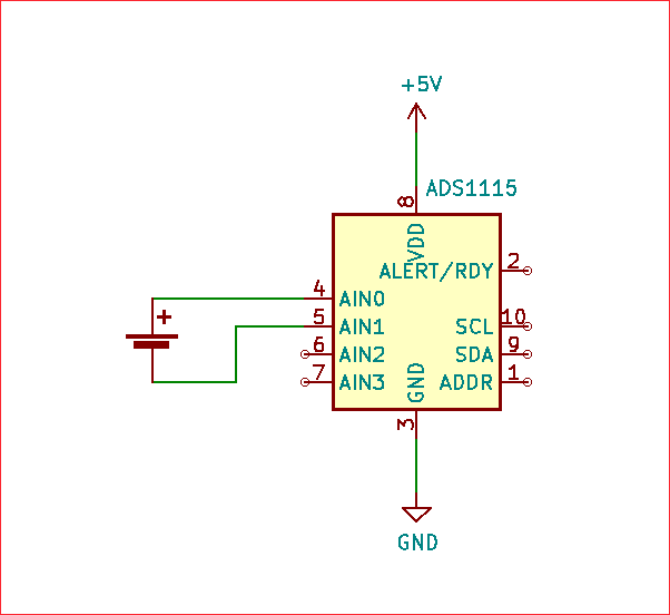
The wiring diagram above shows how to connect an ADS1115 module to an Arduino Uno board. You might have noticed that the ADS1115 module was drawn upside down. But actually, this is the best way to do it. You put them side by side with the ADS1115 module oriented as shown. As a result, you get to use short wires, possibly reducing noise pickup.
The wiring connection above is just the very basic connection. The ADDR pin is not connected at all. As you may recall, the ADDR pin selects the I2C address of the module. Leaving the ADDR pin of the module unconnected actually means it connected to the GND. Please refer to the ADS1115 module schematic above. This is because the ADDR pin of the chip is being pulled down by a 10K resistor to the ground. As a result, the ADS1115 will use the address 0x48. If you want to change the I2C address, you may use the following table as a guide.
The ADDR Pin
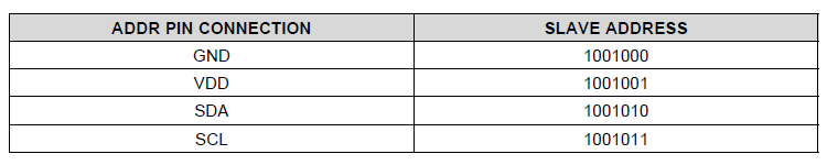
Based on the table above, connecting the ADDR pin to the GND results to an address of 0x48. In order to use the addresses 0x49, 0x4A, or 0x4B, we can connect the ADDR pin to either VDD, SDA, or SCL, respectively. However, using the SCL pin for the 0x4B address needs special software consideration.
If SDA is used as the device address, hold the SDA line low for at least 100 ns after the SCL line goes low to make sure the device decodes the address correctly during I2C communication.
ADS1115 Datasheet (SBAS444D) Page 23
The ALERT/READY Pin
The ALERT/READY pin of the ADS1115 module is also not connected. However, if you intend to use it, you may need to connect it to one of Arduino’s digital I/O pins. The ALERT/READY pin has two uses. First, you can use it for interrupt-driven conversion, where it serves as a data READY signal. And second, you can use it with the programmable output comparator for detecting conversion thresholds. In this case, it serves as an ALERT signal.
ADS1115 Module Arduino Library
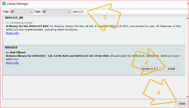
To program the ADS1115 module, we need to install an ADS1115 library. There are several libraries available, two (2) of which are available in the Arduino IDE Library Manager. These are the ADS1115_WE library by Wolfgang Ewald and the ADS1X15 library by Rob Tillaart.
How to Install the ADS1115 Library
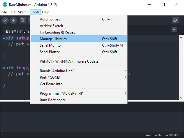
To install the ADS1115 library, click Tools on the Arduino IDE main menu. Then select Manage Libraries.
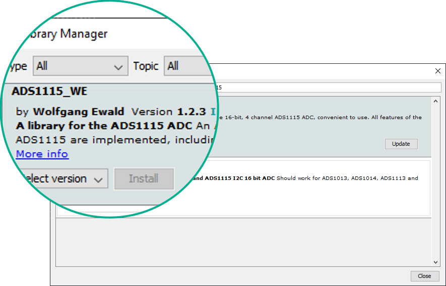
When the Library Manager comes up, search for “ADS1115” in the provided search box. Then, choose which library that you prefer. Afterwards, click on the Install button. And finally, hit the Close button when the Library Manager finishes installing.
The ADS1X15 Library by Rob Tillaart
Rob Tillaart’s ADS1X15 library supports several ADC chips including the single-channel siblings of ADS1115, which are the ADS1113 and the ADS1114. Also, it will work with the 12-bit versions of the chip, which are the ADS1013, ADS1014, and the ADS1015.
First off, to use the library, we include the library’s header file.
#include "ADS1X15.h"
Then, create an ADS1115 object. In creating the object, we need to provide the I2C address which could be 0x48, 0x49, 0x4A, or 0x4B. This depends on the connection of the ADDR pin on the ADS1115 module. See the discussion above.
ADS1115 ADS(0x48);
In the setup() procedure, we initialize the ADS1115.
void setup()
{
ADS.begin();
}
By running the initialization above, several default configuration options for the ADS1115 chip are set. We will discuss some the most important options one by one. If we want to change them later, the library includes functions for changing them.
Programmable Gain Amplifier (Default Gain = 0, FSR = 6.144V)
The ADS1115 chip features a Programmable Gain Amplifier (PGA). You can change the gain setting of the PGA from 0 to 16. However, modifying the gain setting changes the Full Scale Reading (FSR). That is, the maximum voltage that the ADC can measure also changes. The table below shows the relationship between the gain setting and the maximum voltage or Full Scale Reading (FSR).
| PGA Setting | FSR (MaxVoltage) | Comment |
|---|---|---|
| 0 | ±6.144V | DEFAULT |
| 1 | ±4.096V | |
| 2 | ±2.048V | |
| 4 | ±1.024V | |
| 8 | ±0.512V | |
| 16 | ±0.256V |
In order change the default gain setting, and hence, the FSR, we use the setGain(gain) method. Also, if we want to know the current gain setting, we write getGain();
ADS.setGain(16);  //change the gain setting to 16 making the FSR = ±0.256V
uint8_t Gain = ADS.getGain();  //returns the current gain setting index (0, 1, 2, 4, 8, or 16)
Output Data Rate (Default datarate = 4 or 128SPS)
The ADS1115 has a programmable output data rate. The data rate refers to how many times the input is sampled and converted per second. The table below lists the different data rates, from 8 Samples Per Second (SPS) to 860 SPS.
| datarate | SPS | Comment |
|---|---|---|
| 0 | 8 | Slowest |
| 1 | 16 | |
| 2 | 32 | |
| 3 | 64 | |
| 4 | 128 | DEFAULT |
| 5 | 250 | |
| 6 | 475 | |
| 7 | 860 | Fastest |
As with the default gain setting, we can also change the default output data rate of the ADS1115. To change the data rate, we use the command setDataRate(datarate). Also, to find out the current data rate setting, we can use getDataRate().
ADS.setDataRate(7);  //change data rate to maximum 860SPS
uint8_t dataRate = ADS.getDataRate();   //find out the current data rate setting
Operational Mode (Default Single-Shot Mode)
The ADS1115 can be operated in two (2) different modes. One is the Continuous Mode and the other is the Single-shot Mode. In continuous mode, as the name suggests, the ADC constantly samples the input and produces a conversion. However, in single-shot mode, it makes a one-time conversion and goes into a low power mode. This mode is intended for power saving purposes.
To switch from the default single-shot mode setting to continuous mode, we use the method setMode(0). Also, to switch back to the default single-shot mode, we can use setMode(1). And again, to get the current mode setting, we use getMode().
| setMode Value | Operation Mode | Comment |
|---|---|---|
| 0 | Continuous | |
| 1 | Single-shot | DEFAULT |
ADS.setMode(0);  //use continuous mode
ADS.setMode(1);  //use single-shot mode
uint8_t Mode getMode();  //get the currently set operation mode (0 or 1)
Those are the most important configuration settings. To sum up on the initialization command ADS.begin(), the following are the default configuration.
- Gain = 0 resulting to an FSR of 6.144V
- Datarate = 4 which corresponds to 128SPS
- Mode = 1 which is single-shot mode
So far, we have discussed the following lines of code:
#include "ADS1X15.h"
ADS1115 ADS(0x48);

void setup()
{

//Initialization
ADS.begin();


//PGA setting
ADS.setGain(0);
uint8_t Gain = ADS.getGain();

// Data rate
ADS.setDataRate(0);
uint8_t dataRate = ADS.getDataRate();

//Operational Mode
ADS.setMode(0);
uint8_t Mode = ADS.getMode();
}
Let us now go to the actual reading of the ADC conversion results. Recall that the ADS1115 has four (4) input channels. These four (4) channels can be use as four (4) single-ended inputs or they can instead be used as two (2) differential inputs. As a result, the ADS1115 library uses two different procedures for reading the conversion results.
The Single-Ended Read
For single ended reads, we use the function readADC().
loop(){
int16_t rawADC = ADS.readADC();
}
Here is the complete sketch from the library example showing how to use the readADC() function.
#include "ADS1X15.h"

ADS1115 ADS(0x48);

void setup()
{
  Serial.begin(115200);
  Serial.println(__FILE__);
  Serial.print("ADS1X15_LIB_VERSION: ");
  Serial.println(ADS1X15_LIB_VERSION);

  ADS.begin();
}

void loop()
{
  ADS.setGain(0);

  int16_t val_0 = ADS.readADC(0);
  int16_t val_1 = ADS.readADC(1);
  int16_t val_2 = ADS.readADC(2);
  int16_t val_3 = ADS.readADC(3);

  float f = ADS.toVoltage(1);  // voltage factor

  Serial.print("\tAnalog0: "); Serial.print(val_0); Serial.print('\t'); Serial.println(val_0 * f, 3);
  Serial.print("\tAnalog1: "); Serial.print(val_1); Serial.print('\t'); Serial.println(val_1 * f, 3);
  Serial.print("\tAnalog2: "); Serial.print(val_2); Serial.print('\t'); Serial.println(val_2 * f, 3);
  Serial.print("\tAnalog3: "); Serial.print(val_3); Serial.print('\t'); Serial.println(val_3 * f, 3);
  Serial.println();

  delay(1000);
}
The Differential Read
In the differential mode, there are four different commands that are available, depending on the channel pairs to be used.
- readADC_Differential_0_1()
- readADC_Differential_0_3()
- readADC_Differential_1_3()
- readADC_Differential_2_3()
NOTE: ADS1115 cannot measure floating inputs in differential mode.
Please see References at the end of the article.Floating Differential Input
Shown below is the example from the library illustrating how to use readADC_Differential().
#include <ADS1X15.h>

ADS1115 ADS(0x48);

void setup()
{
  Serial.begin(115200);
  Serial.println(__FILE__);
  Serial.print("ADS1X15_LIB_VERSION: ");
  Serial.println(ADS1X15_LIB_VERSION);

  ADS.begin();
  ADS.setGain(0);
}

void loop()
{
  int16_t val_01 = ADS.readADC_Differential_0_1();
  int16_t val_03 = ADS.readADC_Differential_0_3();
  int16_t val_13 = ADS.readADC_Differential_1_3();
  int16_t val_23 = ADS.readADC_Differential_2_3();
  float volts_01 = ADS.toVoltage(val_01);
  float volts_03 = ADS.toVoltage(val_03);
  float volts_13 = ADS.toVoltage(val_13);
  float volts_23 = ADS.toVoltage(val_23);

  Serial.print("\tval_01: "); Serial.print(val_01); Serial.print("\t"); Serial.println(volts_01, 3);
  Serial.print("\tval_03: "); Serial.print(val_03); Serial.print("\t"); Serial.println(volts_03, 3);
  Serial.print("\tval_13: "); Serial.print(val_13); Serial.print("\t"); Serial.println(volts_13, 3);
  Serial.print("\tval_23: "); Serial.print(val_23); Serial.print("\t"); Serial.println(volts_23, 3);
  Serial.println();

  delay(1000);
}
Alternative Arduino Library for ADS1115 Module
There is another good Arduino library for the ADS1115 module. And it is also available on the Arduino IDE Library Manager. The library is named ADS1115_WE which is authored by Wolfgang Ewald. The library is very comprehensive. That is, it is covers all the functions of the ADS1115 ADC chip. Also, besides having a lot of good example sketches, the library is well-documented. As a matter of fact, Wolfgang Ewald has a full article on the ADS1115_WE library on his website.
Related Articles on Using ADS1115 Module with Arduino
1 – Arduino Power Supply Schematic
2 – How to Use MCP4921 DAC with Arduino
3 – How to Use MCP4725 Module with Arduino
4 – How to Use ADS1220 ADC Module with Arduino
References on Using ADS1115 Module with Arduino
ADS1115 Datasheet
ADS1X15 Library by Rob Tillaart
ADS1115_WE by Wolfgang Ewald
Differential Readings (App Note) – explains why a floating input cannot be accurately measured.