In order to safely connect an LED to a circuit, a current limiting resistor is placed in series with the LED. It is quite easy to compute the proper resistor value for the LED if we know some of the parameters.
I play around with Arduino and ESP8266 development boards. As a result, when breadboarding, I usually need LEDs for indicators. First, I use an LED as an indicator if my power supply is ON and has an output voltage. Secondly, I use it as a digital logic level indicator. When the LED is OFF, it indicates a logical 0. If it is ON, it means a logical 1. Finally, I use LEDs to visualize PWM or analog outputs. Their luminance can give you an indication of the approximate values of PWM and analog outputs.
It is necessary to determine the correct value of the current limiting resistor. Improper series resistor value will certainly burn and kill a light emitting diode.
How to Compute Resistor Value for LED Using Resistor-LED Calculator
Datasheet of a Typical 3mm Round LED
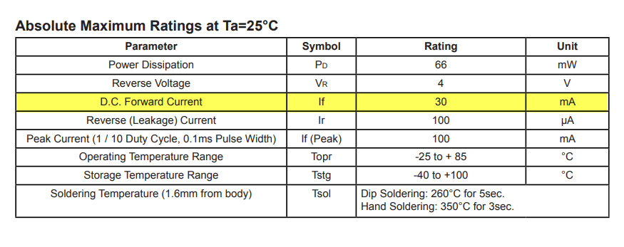
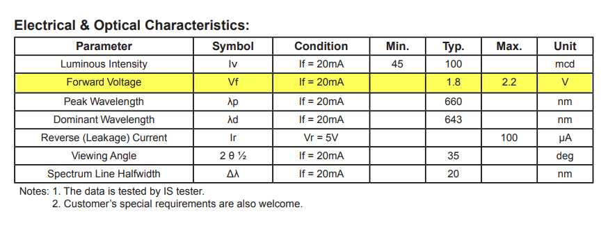
Shown above is an excerpt from the datasheet of a typical 3mm round LED. I highlighted the most important information:
- Maximum Forward Current = 30 ma
- Forward Voltage, Typical = 1.8 V, Maximum = 2.2 V
- Typical Forward Current = 20 ma
CAVEAT
The Arduino GPIO pins have an absolute maximum current rating of 40 mA. Using an LED with 20 mA current is only half of the maximum of 40 mA. Therefore, we are way safe with this amount of current.
On the other hand, ESP8266’s GPIO pins are rated at only 12mA, sink or source. However, this smaller current rating is offset by the lower ESP8266 power of 3.3 Volts. Anyway, a different resistor computation is presented below for LEDs to be used for ESP8266 development boards.
Formula and Sample Computation
Ohm’s law states that the current through a conductor between two points is directly proportional to the voltage across the two points.
Wikipedia
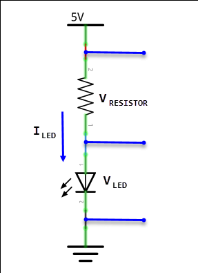
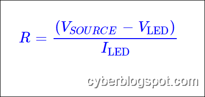
Ohm’s Law states that I = V/R. Since we are interested in computing the value of R in the circuit depicted above, the basic formula is transposed to: R = V/I.
If we study the schematic diagram, there are two points to remember. One, that the current (I) flowing thru the resistor is the same current flowing thru the LED. And second, the source voltage of 5V is divided between the voltage across the resistor and the voltage across the LED.
If we want to limit the current to the LED to its typical value of 20 ma, based on the datasheet, its forward voltage will be 1.8 V. Because the total voltage across the resistor-LED circuit is 5 V and the voltage across the LED is 1.8 V, it follows that the voltage across the unknown resistor is 5 V minus 1.8 V = 3.2 V. See the top part or the numerator of the right hand side of the formula below.
And since we know that the current thru the resistor is the same as the current flowing thru the LED which is 20 mA, we can now compute the resistor value,
R = 3.2 V / 20 mA = 3.2 V / .020 A = 160 Ohms
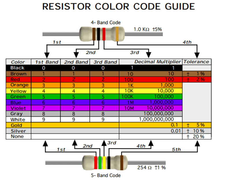
If a 160 Ohms resistor is not available, the nearest higher resistor value we can use is 168 Ohms, color coded brown-gray-brown.
Table of Computed Resistor Values for Arduino Use
| Current | V forward | R Value Computed | R Value Nearest Higher |
| 20 mA | 1.8 V | 160 Ohms | 180 Ohms |
| 15 mA | 1.8 V | 213.33 Ohms | 220 Ohms |
| 10 mA | 1.75 V | 325 Ohms | 330 Ohms |
| 5 mA | 1.70 V | 660 Ohms | 680 Ohms |
Resistor Values for ESP8266
Resistor Voltage = 3.3 V – 1.8 V = 1.5 V
Resistor Value = 1.5 V / 10 mA = 1.5 V / .010 A = 150 Ohms
| Current | V forward | R Value Computed | R Value Nearest Higher |
| 10 mA | 1.75 | 155 | 180 |
| 8 mA | 1.75 | 193.75 | 220 |
| 5 mA | 1.70 | 320 | 330 |
| 3 mA | 1.65 | 550 | 560 |
Resistor Color Code Guide
Resistor Pack From Makerlab

Resistor Kit – 1/4W Metal Film
Values Included:
- 10Ω, 22Ω, 47Ω, 100Ω, 150Ω, 200Ω,
- 220Ω, 270Ω, 330Ω, 470Ω, 510Ω, 680Ω,
- 1KΩ, 2KΩ, 2K2Ω, 3K3Ω, 4K7Ω, 5K1Ω, 6K8Ω,
- 10KΩ, 20KΩ, 47KΩ, 51KΩ, 68KΩ, 100KΩ,
- 220KΩ, 300KΩ, 470KΩ, 680KΩ, 1MΩ
Related Articles on How to Compute Resistor Value for LED
NodeMCU V3 ESP8266 Pinout and Configuration
References on How to Compute Resistor Value for LED
Resistors on Wikipedia
LED on Wikipedia