It is possible to make a digital clock out of an ESP-01 ESP8266 module synchronized with NTP (Network Time Protocol) and using a 20×4 LCD for displaying the current date and time.
At first glance, it looks like an impossible task because the ESP-01 module has only a few GPIO pins. The ESP-01 module has only 8 pins: two (2) for the power supply, one for reset, one for CH_PD (Chip Enable/Power Down), and four (4) GPIO pins.
The four (4) GPIOs available on the ESP-01 are the GPIO-0, GPIO-1, GPIO-2, and GPIO-3. GPIO-1 is used as the TX line and GPIO-3 is the RX line of the ESP8266’s UART. GPIO-0 and GPIO-2 also have special functions. They select the boot modes of ESP8266.
The project is possible if two conditions are met:
- we use an LCD display with I2C interface (two-wire interface)
- we use the LiquidCrystal_I2C library that was modded to use non-I2C pins of ESP8266
Since an LCD display with I2C interface uses only two pins, it can be connected to the ESP-01 module using GPIO-0 and GPIO-2. There is a LiquidCrystal_I2C library version that turns GPIO-0 as SDA pin and GPIO-2 as SCL pin for the I2C communication channel.
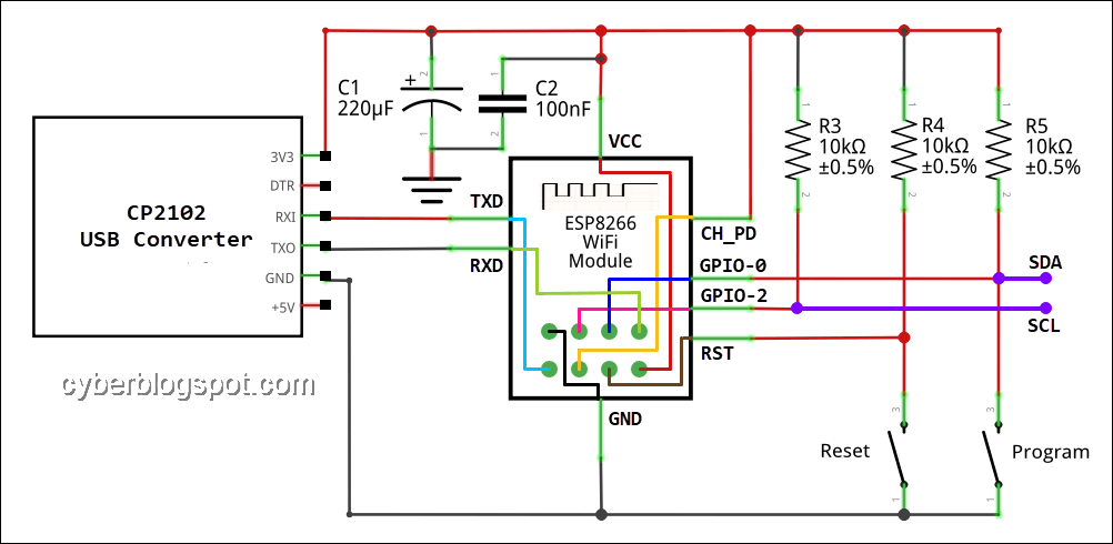
The circuit above shows the schematic diagram of an ESP-01 connected with a USB to TTL converter. With this connection, the ESP-01 module can be programmed thru the USB converter. The diagram also shows the SDA and SCL connection points where an LCD using an I2C interface can be connected.
Arduino IDE Program
/*
 * ESP-01_NTP_Clock_LCD.ino
 *
 * By cyberblogspot.com 05 Feb 2020
 * Digital Clock with LCD and Serial Monitor Display
 * Clock synchronized with Network Time Protocol
 *
 * Based on the example from Time Library
 * Modified for ESP-01 module using GPIO-0 and GPIO-2 as I2C pins
 * From:
 * TimeNTP_ESP8266WiFi.ino
 * Example showing time sync to NTP time source
 *
 * This sketch uses the ESP8266WiFi library
 */

#include <TimeLib.h>  //Arduino Time Library
                      //https://github.com/PaulStoffregen/Time
#include <ESP8266WiFi.h>
#include <WiFiUdp.h>

#include <LiquidCrystal_I2C.h> //This is for non-I2C pins used as I2C
                               //https://github.com/agnunez/ESP8266-I2C-LCD1602
#include <Streaming.h> // shorten serial print command

LiquidCrystal_I2C lcd(0x27, 20, 4);

const char ssid[] = "myssid";  //  your network SSID (name)
const char pass[] = "password";       // your network password

// NTP Servers:
static const char ntpServerName[] = "ntp.pagasa.dost.gov.ph"; //us.pool.ntp.org
//static const char ntpServerName[] = "time.nist.gov";
//static const char ntpServerName[] = "time-a.timefreq.bldrdoc.gov";
//static const char ntpServerName[] = "time-b.timefreq.bldrdoc.gov";
//static const char ntpServerName[] = "time-c.timefreq.bldrdoc.gov";

const int timeZone = 8; //1    // Central European Time
//const int timeZone = -5;  // Eastern Standard Time (USA)
//const int timeZone = -4;  // Eastern Daylight Time (USA)
//const int timeZone = -8;  // Pacific Standard Time (USA)
//const int timeZone = -7;  // Pacific Daylight Time (USA)

WiFiUDP Udp;
unsigned int localPort = 8888;  // local port to listen for UDP packets

// Function prototypes, old school
time_t getNtpTime();
void digitalClockDisplay();
void printDigits(int digits);
void sendNTPpacket(IPAddress &address);

void setup()
{
  Serial.begin(74880); // if used as sync provider via serial, don't
                       // use higher baud, causes erroneous data
  while (!Serial) ; // Needed for Leonardo only
  delay(250);

  //Only difference from original library is the begin parameters
  lcd.begin(0, 2); // Initialize I2C LCD module (SDA = GPIO0, SCL = GPIO2)
  lcd.backlight(); // Turn backlight ON

  Serial << "ESP-01 NTP Clock" << endl;
  lcd.setCursor(0,0);
  lcd << "ESP-01 NTP Clock";
  Serial << "Connecting to ";
  lcd.setCursor(0,1);
  lcd << "Connecting: ";
  Serial << ssid << endl;
  lcd << ssid;
  WiFi.begin(ssid, pass);

  lcd.setCursor(0, 2);
  int iLcdCol = 0;
  while (WiFi.status() != WL_CONNECTED) {
    delay(250); //500
    Serial << ".";
    lcd << ".";
    iLcdCol++;  // stop too many dots from line overrun
    if (iLcdCol == 10){
      iLcdCol = 0;
      lcd.setCursor(0, 2);
      lcd << "          "; // print 10 spaces to delete previous dots
      lcd.setCursor(0, 2);
      }
  }

  lcd.setCursor(0,2);
  Serial << endl << "IP number assigned by DHCP is ";
  lcd << "IP: ";
  Serial << WiFi.localIP() << endl;
  lcd << WiFi.localIP();
  Serial << "Starting UDP" << endl;
  lcd.setCursor(0,3);
  lcd << "UDP: ";
  Udp.begin(localPort);
  Serial << "Local port: " << Udp.localPort() << endl;
  lcd << Udp.localPort();

  setSyncProvider(getNtpTime);
  setSyncInterval(60);//default 300 seconds - 5mins

  delay(3000); //3 seconds to let user read lcd messages
  lcd.clear();
}

time_t prevDisplay = 0; // when the digital clock was displayed

void loop()
{
  if (timeStatus() != timeNotSet) {
    if (now() != prevDisplay) { //update the display only if time has changed
      prevDisplay = now();
      digitalClockDisplay();
    }
  }
}

void digitalClockDisplay()
{
  // digital clock display of the time
  int y, mo, d, h, m, s;
  time_t tNow;
  tNow = now();
  y = year(tNow);
  mo = month(tNow);
  d = day(tNow);
  h = hour(tNow);
  m = minute(tNow);
  s = second(tNow);

  // Display time and date on serial monitor
  Serial << h;
  printDigits(m);
  printDigits(s);
  Serial << ' ' << d << '.' << mo << '.' << y << endl;

  // Display time on LCD line 1
  lcd.setCursor(0,0);
  lcd << "Time: ";
  if (h < 10) lcd << '0';
  lcd << h << ':';
  if (m < 10) lcd << '0';
  lcd << m << ':';
  if (s < 10) lcd << '0';
  lcd << s;

  // Print day string on LCD line 2
  // need to pad short daystring with spaces to clear lcd line
  lcd.setCursor(0,1);
  lcd << "Day : ";

  char szDayStr[10];
  char cPad = ' '; // space pad

  strcpy(szDayStr, dayStr(weekday())); //get day string

  int iStrLen = strlen(szDayStr);
  while (iStrLen < 9) // pad up to nine 9 chars
    {
    strncat(szDayStr, &cPad,1);
    iStrLen = strlen(szDayStr);
    }

  lcd << szDayStr;

  // Print date on LCD line 3
  lcd.setCursor(0, 2);
  lcd << "Date: " << d << ' ' << monthShortStr(mo) << ' ' << y;

  //Display timeStatus on LCD line 4
  // 0-timeNotSet 1-timeNeedSync 2-timeSet
  lcd.setCursor(0, 3);
  lcd << "Status: ";

  int status = timeStatus();

  switch (status) {
    case 0:
      lcd << "timeNotSet  "; // spaces to delete old message
      break;

    case 1:
      lcd << "timeNeedSync";
      break;

    default:
      lcd << "timeSet     ";
      break;
    }
}

void printDigits(int digits)
{
  // utility for digital clock display: prints preceding colon and leading 0
  Serial << ":";
  if (digits < 10)
    Serial << '0';
  Serial << digits;
}

/*-------- NTP code ----------*/

const int NTP_PACKET_SIZE = 48; // NTP time is in the first 48 bytes of message
byte packetBuffer[NTP_PACKET_SIZE]; //buffer to hold incoming & outgoing packets

time_t getNtpTime()
{
  IPAddress ntpServerIP; // NTP server's ip address

  while (Udp.parsePacket() > 0) ; // discard any previously received packets
  Serial.println("Transmit NTP Request");
  // get a random server from the pool
  WiFi.hostByName(ntpServerName, ntpServerIP);
  Serial.print(ntpServerName);
  Serial.print(": ");
  Serial.println(ntpServerIP);
  sendNTPpacket(ntpServerIP);
  uint32_t beginWait = millis();
  while (millis() - beginWait < 1500) {
    int size = Udp.parsePacket();
    if (size >= NTP_PACKET_SIZE) {
      Serial.println("Receive NTP Response");
      Udp.read(packetBuffer, NTP_PACKET_SIZE);  // read packet into the buffer
      unsigned long secsSince1900;
      // convert four bytes starting at location 40 to a long integer
      secsSince1900 =  (unsigned long)packetBuffer[40] << 24;
      secsSince1900 |= (unsigned long)packetBuffer[41] << 16;
      secsSince1900 |= (unsigned long)packetBuffer[42] << 8;
      secsSince1900 |= (unsigned long)packetBuffer[43];

      return secsSince1900 - 2208988800UL + timeZone * SECS_PER_HOUR;
    }
  }
  //1500 secs timed out, return 0
  //Needs to return 0 so setTime does not proceed to
  //sync with unknown value, see now() in time.cpp
  Serial.println("No NTP Response :-(");
  return 0; // return 0 if unable to get the time
}

// send an NTP request to the time server at the given address
void sendNTPpacket(IPAddress &address)
{
  // set all bytes in the buffer to 0
  memset(packetBuffer, 0, NTP_PACKET_SIZE);
  // Initialize values needed to form NTP request
  // (see URL above for details on the packets)
  packetBuffer[0] = 0b11100011;   // LI, Version, Mode
  packetBuffer[1] = 0;     // Stratum, or type of clock
  packetBuffer[2] = 6;     // Polling Interval
  packetBuffer[3] = 0xEC;  // Peer Clock Precision
  // 8 bytes of zero for Root Delay & Root Dispersion
  packetBuffer[12] = 49;
  packetBuffer[13] = 0x4E;
  packetBuffer[14] = 49;
  packetBuffer[15] = 52;
  // all NTP fields have been given values, now
  // you can send a packet requesting a timestamp:
  Udp.beginPacket(address, 123); //NTP requests are to port 123
  Udp.write(packetBuffer, NTP_PACKET_SIZE);
  Udp.endPacket();
}
Related Articles on ESP-01 ESP8266 NTP Clock with LCD Display
Arduino Reference and Resources
How to Set up Arduino IDE for ESP8266 Programming
NodeMCU V3 ESP8266 Pinout and Configuration
How to Test NodeMCU V3 Using Esptool
How to Install Arduino IDE on Windows 10
How to Save and Restore ESP8266 and ESP32 Firmware
NodeMCU ESP-32S Pin Configuration
How to Use MCP4725 Module with Arduino
How to Use ADS1220 ADC Module with Arduino
References on ESP-01 ESP8266 NTP Clock with LCD Display
Arduino IDE
ESP8266 on Wikipedia
Careful with that sync interval time. It is in milliseconds. So setting it to 60 does NOT set it to 5 minutes. It sets it to hit up the server quite frequently. Essentially every time it want to update the time. Multiple times per second is possible. This can get your IP banned by ntp.org.