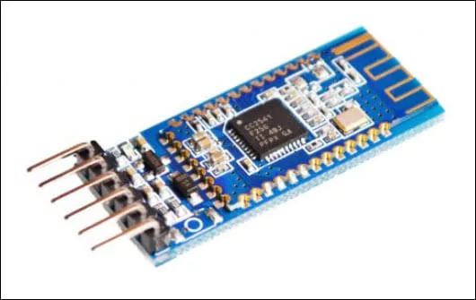
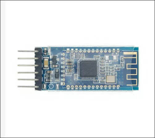
The AT-09 BLE module is a Bluetooth Low Energy transceiver that uses the BLE chip CC2541. It is compatible with the popular HM-10 BLE Bluetooth module. The module is used to provide Bluetooth capability to microcontrollers lacking Bluetooth support. As an example, we will connect an AT-09 BLE board on an Arduino board and use a smartphone to control an LED on the Arduino board.
Wiring Diagram to Use AT-09 BLE with Arduino and Smartphone
To use an AT-09 BLE with Arduino and a smartphone, connect the AT-09 module to the Arduino board using the schematic diagram below. In this article, I am using an Arduino Nano board as an example. However, you may use any Arduino board that is available. As a matter of fact, you may use ANY microcontroller at your disposal. On my next project, I would connect an AT-09 BLE module to an ATtiny85 chip for a low-current car central door lock system.
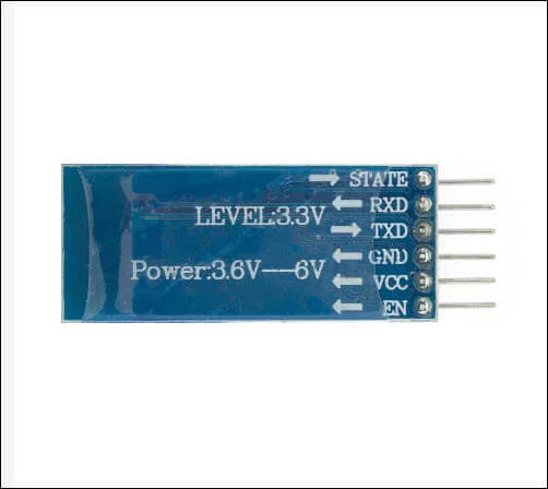
As shown by the Fritzing breadboard and the KiCad schematic diagram below, there are only four terminals that we need to connect. These are the RX, TX, GND, and VCC.
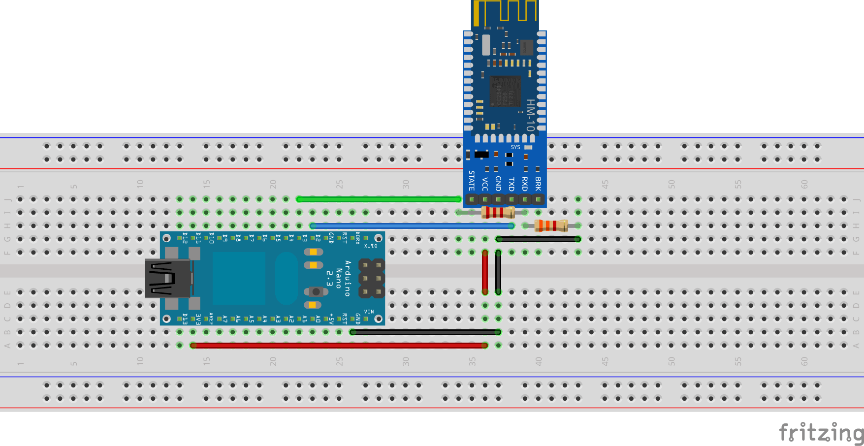
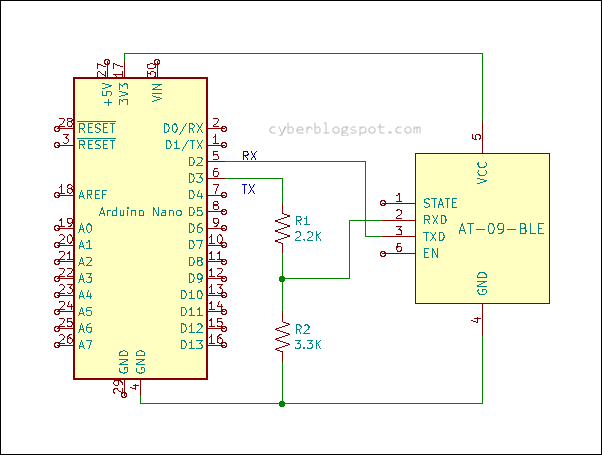
Referring to Figure 4 above, the Arduino Nano’s D2 and D3 terminals are labelled as RX (Receiver) and TX (Transmitter) respectively. These terminals will simulate a UART port and will be assigned as RX and TX ports thru software (software serial). The choice of D2 and D3 is arbitrary and you may use any two (2) available digital IO pins except D0 and D1 (hardware serial ports).
The ports D0 and D1 (RX and TX) may not be used because we will use the Arduino IDE Serial Monitor. Remember that the ports D0 and D1 are connected to the USB port of the Arduino board and are connected to your computer for uploading sketches. Therefore, in order to use the Serial Monitor, the ports D0 and D1 must be free (unused, no external circuitry). We will use the Serial Monitor as input and output device for interacting with the AT-09 BLE module.
Take note that the Arduino Nano’s RX and TX (D2 and D3) terminals are cross-wired with the RX and TX terminals of the AT-09 BLE module. That is, the RX terminal of the Arduino Nano connects to the TX terminal of the AT-09 BLE module. Vice versa, the TX terminal of the Arduino Nano is wired to the RX terminal of the AT-09 BLE module.
Resistors R1 and R2 are used as logic level translators. The circuit reduces the 5V output from the Arduino Nano’s TX port to the 3V logic level needed by the AT-09 BLE board. However, the RX port does not need a logic level translation since it is receiving a lower 3V logic that it can sufficiently handle.
Smartphone App for Use with AT-09 BLE Module and Arduino Board
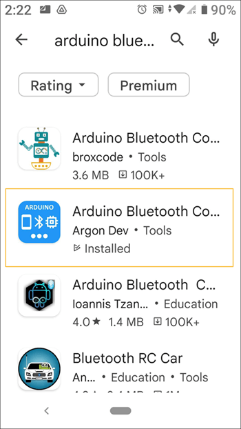
There are many smartphone apps available for controlling a Bluetooth module but as a starter, we will use the Arduino Bluetooth Controller (HM-10 Module). Since this app is specifically for HM-10 module and the AT-09 module being compatible with the HM-10 module, the app works perfectly well with the AT-09 BLE module. If you want to make your own Android smartphone app, you can create one even if you are not a programmer. Take a look at MIT App Inventor.
Before we start programming the Arduino board, download and install the Arduino Bluetooth Controller from the Google Play Store. There are many similarly named Bluetooth controllers on the Google Play Store, so look for the one made by Argon Dev. See Figure 5 below.
Quick Test on AT-09 BLE Module
After downloading the Bluetooth controller app, power up the Arduino board by plugging it into the computer’s USB port. When the AT-09 BLE module is powered up, you should see the onboard LED flashing. The flashing LED light indicates it is transmitting and advertising its presence. Open the Bluetooth controller app.
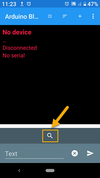
Click on the search icon. See Figure 6 above.
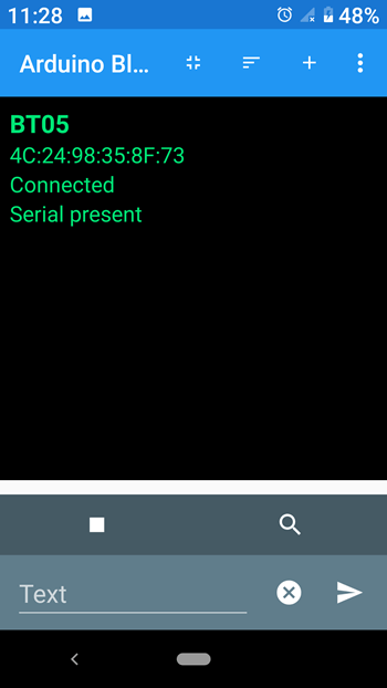
When the AT-09 BLE module connects to the Bluetooth controller, you should see the displayed message turning into green, similar to the one displayed on Figure 7. BT05 is the Bluetooth device name of the AT-09 BLE module and the 12-digit hex number is its Bluetooth MAC address. Also, look at the AT-09 BLE module. You should see the LED on the board stop flashing and stay steadily lit.
If you can connect to the AT-09 BLE module using a smartphone, you can now proceed to programming the Arduino board. We will first program the Arduino Nano to play around with the AT commands. After that, we will insert additional codes to the sketch to control the Arduino’s onboard LED using the smartphone.
The AT-09 BLE Module AT Commands
AT commands are instructions sent to the Bluetooth module to display and change its configuration. For example, if we want to display or change its device name, we send it the command AT+NAME. If we want to display its Bluetooth MAC address, we use the command AT+LADDR. We will learn more about these AT commands after uploading the following sketch to the Arduino board.
/* cyberblogspot.com 21Jan2023
 *
 * Program to send AT commands to AT-09 BLE module
 * and display the responses on the Serial Monitor
 *
 * RX and TX cross wired
 * 2k and 3k voltage divider on AT-09 RX (reduce 5V to 3V)
 */

#include <SoftwareSerial.h>
SoftwareSerial bleSerial(2, 3); //D2 is RX, D3 is TX

char bleData;  //storage for AT-09 data
String mData;  //storage for AT-09 and serial monitor data

void setup() {
  Serial.begin(115200);   //initialize serial monitor
  bleSerial.begin(9600);  //and BLE serial port, default AT-09 baud rate is 9600 baud

  Serial.println("AT-09 BLE module ready");
}

void loop() {
  if (Serial.available()) {
    mData = Serial.readString(); //read serial monitor input
    Serial.println(mData);       //echo keyboard input to serial monitor
    bleSerial.println(mData);    //send keyboard input to AT-09 module
  }

  bleSerial.listen();                  //listen to the AT-09 port
  while (bleSerial.available() > 0) {  //if AT-09 data available
    bleData = bleSerial.read();        //read character and
    mData = String(bleData);           //convert to string format
    Serial.print(mData);               //display to serial monitor
  }
}
The sketch above will let us type AT commands on the Arduino IDE’s Serial Monitor and send it to the AT-09 BLE module. Anything that we type on the Serial Monitor will be echoed back (displayed) on the Serial Monitor. At the same time, it will be sent to the AT-09 module. When the AT-09 module replies in response to the AT commands sent, it will also be displayed on the Serial Monitor.
The program starts by including the library SoftwareSerial. It is a built-in Arduino library so you do not need to download or install it.
#include <SoftwareSerial.h>
Next, we create the SoftwareSerial object bleSerial.
SoftwareSerial bleSerial(2, 3); //D2 is RX, D3 is TX
As per discussion above on the wiring diagram (see Figure 4 above), the digital IO port D2 will be used as an RX port and digital IO port D3 will become a TX port. Because the hardware UART ports D1 and D2 are being used by the Serial Monitor, we are creating an additional UART port via software. This additional port is where the AT-09 BLE module is connected.
void setup() {
  Serial.begin(115200);   //initialize serial monitor
  bleSerial.begin(9600);  //and BLE serial port, default AT-09 baud rate is 9600 baud

  Serial.println("AT-09 BLE module ready");
}
In the setup() routine, the hardware UART port “Serial” and the software UART port “bleSerial” are initialized. Note that the “bleSerial” speed is set to 9600 baud only because the module is configured to use that speed by default.
void loop() {
  if (Serial.available()) {
    mData = Serial.readString(); //read serial monitor input
    Serial.println(mData);       //echo keyboard input to serial monitor
    bleSerial.println(mData);    //send keyboard input to AT-09 module
  }

  bleSerial.listen();                  //listen to the AT-09 port
  while (bleSerial.available() > 0) {  //if AT-09 data available
    bleData = bleSerial.read();        //read character and
    mData = String(bleData);           //convert to string format
    Serial.print(mData);               //display to serial monitor
  }
}
Finally on the loop() procedure, the program is very simple. The program checks if there is input on the Serial Monitor. If there is, it sends the data to the AT-09 BLE module. In the same manner but vice versa, it checks for any available data from the AT-09 module and sends it to the Serial Monitor.
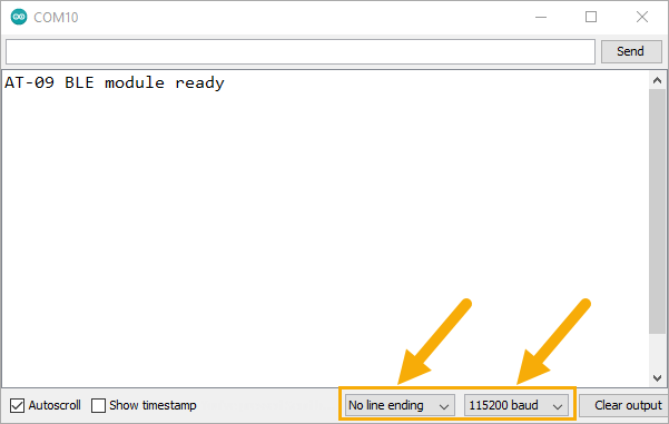
Upload the sketch to the Arduino board and then open the Arduino IDE Serial Monitor. Change the Serial Monitor settings to “No line ending” and “115200 baud” as in Figure 8.
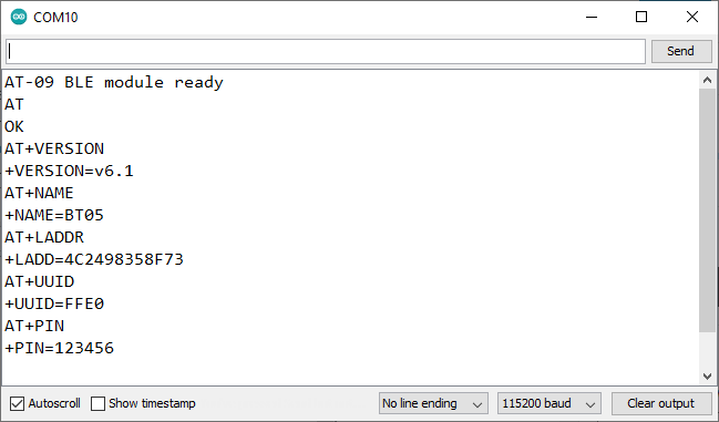
Type “AT” and press the ENTER key, and you should get the message “OK”. That means that the AT-09 BLE module is accepting AT commands.
Type “AT+VERSION” and the firmware version of the AT-09 module will be displayed on the Serial Monitor.
Type “AT+NAME” and the response should be the default device name of “BT05”.
Type “AT+LADDR” and see the module’s local address or Bluetooth MAC address.
Type “AT+UUID” and the Universal Unique Identifier is displayed which is hex FFE0.
Type “AT+PIN” and the serial monitor will display the default PIN of 123456 used for pairing with other Bluetooth devices.
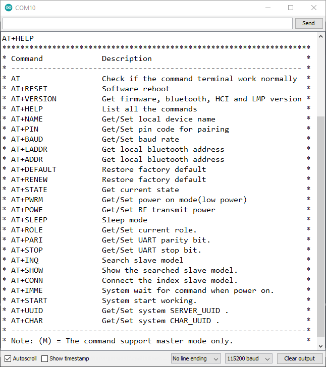
Finally, type “AT+HELP” and the Serial Monitor will display all the available AT commands that the AT-09 BLE module supports.
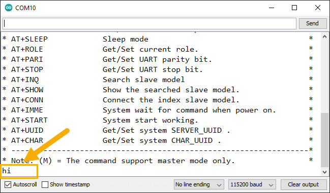
Now, open the Arduino Bluetooth Controller. Connect to the AT-09 BLE module, type the word “hi”, and press the SEND button.
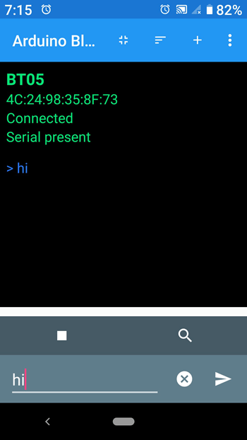
You should see the word “hi” in the Arduino Serial Monitor as shown in Figure 12.
Type “hello” on the Arduino Serial Monitor. You will see the word “hello” on your smartphone.
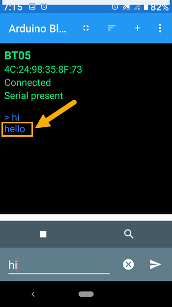
It must be clear now that you can send messages from your smartphone to your Arduino board. And the other way around, you can send messages from the Arduino board to your smartphone.
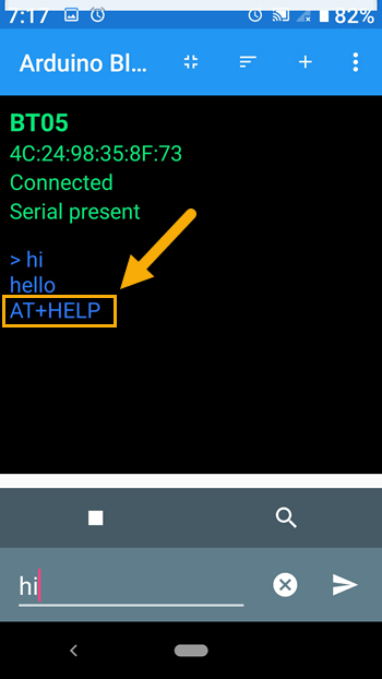
Let us go back to the Serial Monitor and type the AT command “AT+HELP” again.
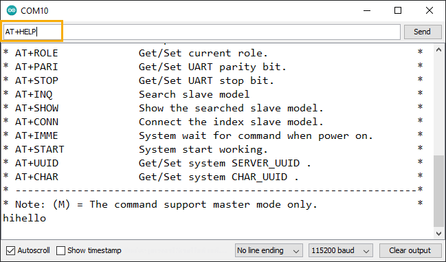
The word “AT+HELP” was echoed back on the Serial Monitor as expected (Figure 15). It was also sent to the smartphone app Arduino Bluetooth Controller (Figure 16). However, the AT-09 BLE module did not respond to the AT command “AT+HELP” to display the list of AT commands. This shows that the AT-09 BLE module will only respond to AT commands when it is not connected to any device. And to prove this to yourself, disconnect the Arduino Bluetooth Controller from the AT-09 module and type the “AT+HELP” again on the Serial Monitor and see what happens.

Controlling the Arduino Onboard LED with Smartphone
Now, we are ready to control the the AT-09 BLE module on the Arduino board using our smartphone. We are going to turn on and off the built-in LED on the Arduino Nano board. To do this, we will add a few lines of code to our sketch.
pinMode(13, OUTPUT);    //set D13 as output where built-in LED is connected
digitalWrite(13, LOW);  //initially turn off LED
In the setup() procedure, we will insert the two lines of code shown above. Since the Arduino Nano built-in LED is connected to the digital IO port D13, we will set it up as an OUTPUT port. Then send a digitalWrite() command to initially turn it off.
if (mData == "0") {
    digitalWrite(13, LOW);   //turn off LED
  }

  if (mData == "1") {
    digitalWrite(13, HIGH);  //turn on LED
  }
Then, we will also insert codes in the loop() procedure to check the messages that are being received by the AT-09 BLE module and the Arduino board. If a “0” message is received, the Arduino board turns off the LED, and if a “1” message comes in, the LED will be turned on.
Figure 17 shows how the additional codes are inserted into the previous sketch.

The complete Arduino IDE source code on how to use AT-09 BLE module with Arduino and smartphone.
/* cyberblogspot.com 21Jan2023
 *
 * Program to send AT commands to AT-09 BLE module
 * and display the responses on the Serial Monitor
 *
 * RX and TX cross wired
 * 2k and 3k voltage divider on AT-09 RX (reduce 5V to 3V)
 */

#include <SoftwareSerial.h>
SoftwareSerial bleSerial(2, 3); //D2 is RX, D3 is TX

char bleData;  //storage for AT-09 data
String mData;  //storage for AT-09 and serial monitor data

void setup() {
  Serial.begin(115200);   //initialize serial monitor
  bleSerial.begin(9600);  //and BLE serial port, default AT-09 baud rate is 9600 baud

  pinMode(13, OUTPUT);    //set D13 as output where built-in LED is connected
  digitalWrite(13, LOW);  //initially turn off LED

  Serial.println("AT-09 BLE module ready");
}

void loop() {
  if (Serial.available()) {
    mData = Serial.readString(); //read serial monitor input
    Serial.println(mData);       //echo keyboard input to serial monitor
    bleSerial.println(mData);    //send keyboard input to AT-09 module
  }

  bleSerial.listen();                  //listen to the AT-09 port
  while (bleSerial.available() > 0) {  //if AT-09 data available
    bleData = bleSerial.read();        //read character and
    mData = String(bleData);           //convert to string format
    Serial.print(mData);               //display to serial monitor
  }

  if (mData == "0") {
    digitalWrite(13, LOW);   //turn off LED
  }

  if (mData == "1") {
    digitalWrite(13, HIGH);  //turn on LED
  }
}
How to Set Up the Arduino Bluetooth Controller
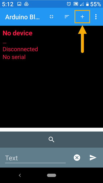
To set up the Arduino Bluetooth Controller, open the app and click on the plus icon (+) to open the template designer.
Enter the Name, Text, Description, and select a color. You may use a different name, description and color but the text must be “1”, in order to match with the code of the sketch. Then click on Save button. Refer to Figure 19 below.
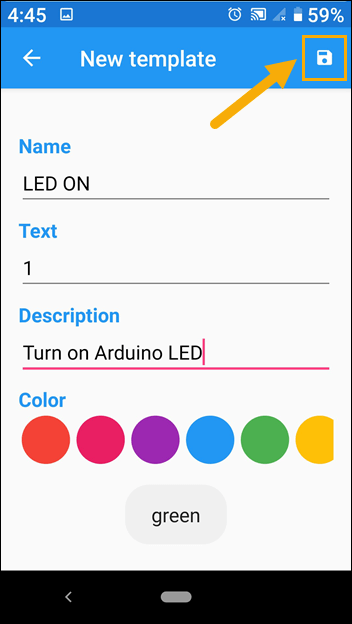
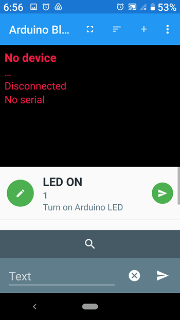
Figure 20 shows the saved template with the completed first button. If you made a mistake, long press on the saved button, delete it, and start all over again.
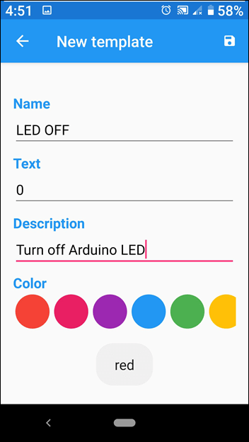
Repeat the above procedure for the second button. Refer to Figure 21 below.
After saving the second button, you should have a display similar to Figure 22.
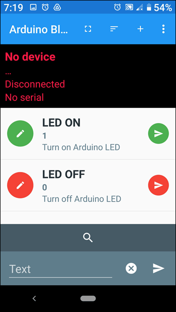
That completes the setup for the Arduino Bluetooth Controller and you may now test it for use with AT-09 BLE, Arduino and a smartphone.
Related Articles on How to Use AT-09 BLE with Arduino and Smartphone
How to Use Arduino as ISP Programmer
How to Control ESP-01 thru a Router
How to Control ESP-01 Without a Router
How to Install Esptool on Windows 10
How to Save and Restore ESP8266 and ESP32 Firmware
NodeMCU V3 ESP8266 Pinout and Configuration
NodeMCU ESP-32S Pin Configuration
Digispark ATtiny85 Pinout and Configuration
How to Program Digispark ATtiny85 Board with Arduino IDE
How to Enable Serial Monitor on Digispark ATtiny85
References on How to Use AT-09 BLE with Arduino and Smartphone
Bluetooth Low Energy on Wikipedia
HM-10 Datasheet
Arduino Bluetooth Controller (HM-10 Module)